参数资料
| 型号: | EL1508CM-T13 |
| 厂商: | Intersil |
| 文件页数: | 5/18页 |
| 文件大小: | 0K |
| 描述: | IC LINE DRIVER ADSL 20-SOIC |
| 标准包装: | 1,000 |
| 类型: | 驱动器 |
| 驱动器/接收器数: | 1/0 |
| 电源电压: | 5 V ~ 12 V |
| 安装类型: | 表面贴装 |
| 封装/外壳: | 20-SOIC(0.295",7.50mm 宽) |
| 供应商设备封装: | 20-SO |
| 包装: | 带卷 (TR) |
13
FN7014.5
March 26, 2007
Applications Information
The EL1508 consists of two high-power line driver amplifiers
that can be connected for full duplex differential line
transmission. The amplifiers are designed to be used with
signals up to 4MHz and produce low distortion levels. The
EL1508 has been optimized as a line driver for ADSL CO
application. The driver output stage has been sized to
provide full ADSL CO power level of 20dBM onto the
telephone lines. Realizing that the actual peak output
voltages and currents vary with the line transformer turns
ratio, the EL1508 is designed to support 450mA of output
current which exceeds the level required for 1:2 transformer
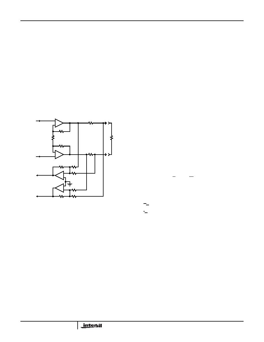
ratio. A typical ADSL interface circuit is shown in Figure 43
below. Each amplifier has identical positive gain
connections, and optimum common-mode rejection occurs.
Further, DC input errors are duplicated and create common-
mode rather than differential line errors.
Input Connections
The EL1508 amplifiers are somewhat sensitive to source
impedance. In particular, they do not like being driven by
inductive sources. More than 100nH of source impedance
can cause ringing or even oscillations. This inductance is
equivalent to about 4” of unshielded wiring, or 6” of
unterminated transmission line. Normal high-frequency
construction obviates any such problem.
Power Supplies and Dissipation
Due to the high power drive capability of the EL1508, much
attention needs to be paid to power dissipation. The power
that needs to be dissipated in the EL1508 has two main
contributors. The first is the quiescent current dissipation.
The second is the dissipation of the output stage.
The quiescent power in the EL1508 is not constant with
varying outputs. In reality, 50% of the total quiescent supply
current needed to power each driver is converted in to output
current. Therefore, in the equation below we should subtract
the average output current, IO, or 1/2 IQ, whichever is the
lowest. We’ll call this term IX.
Therefore, we can determine a quiescent current with the
equation:
where:
VS is the supply voltage (VS+ to VS-)
IS is the operating supply current (IS+ - IS-) / 2
IX is the lesser of IO or 1/2 IQ
The dissipation in the output stage has two main
contributors. Firstly, we have the average voltage drop
across the output transistor and secondly, the average
output current. For minimal power dissipation, the user
should select the supply voltage and the line transformer
ratio accordingly. The supply voltage should be kept as low
as possible, while the transformer ratio should be selected
so that the peak voltage required from the EL1508 is close to
the maximum available output swing. There is a trade off,
however, with the selection of transformer ratio. As the ratio
is increased, the receive signal available to the receivers is
reduced.
Once the user has selected the transformer ratio, the
dissipation in the output stages can be selected with the
following equation:
where:
VS is the supply voltage (VS+ to VS-)
VO is the average output voltage per channel
IO is the average output current per channel
The overall power dissipation (PDISS) is obtained by adding
PDquiescent and PDtransistor.
Estimating Line Driver Power Dissipation in ADSL
CO Applications
Figure 44 on the following page shows a typical ADSL CO
line driver implementation. The average line power
requirement for the ADSL CO application is 20dBM
(100mW) into a 100
Ω line. The average line voltage is
3.16VRMS. The ADSL DMT peak to average ratio (crest
factor) of 5.3 implies peak voltage of 16.7V into the line.
Using a differential drive configuration and transformer
coupling with standard back termination, a transformer ratio
of 1:1 is selected. With 1:1 transformer ratio, the impedance
across the driver side of the transformer is 100
Ω, the
average voltage is 3.16VRMA and the average current is
31.6mA. The power dissipated in the EL1508 is a
FIGURE 43. TYPICAL LINE INTERFACE CONNECTION
-
+
-
+
-
+
-
+
RECEIVE
OUT -
RECEIVE
OUT +
DRIVER
INPUT+
2RG
RF
R
RIN
R
RIN
RF
ROUT
LINE +
LINE -
RECEIVE
AMPLIFIERS
ZLINE
DRIVER
INPUT-
P
Dquiescent
V
S
I
S
21
X
–
()
×
=
P
Dtransistors
2I
O
V
S
2
-------
V
O
–
×
=
EL1508
相关PDF资料 |
PDF描述 |
|---|---|
| VI-B5R-MW-F1 | CONVERTER MOD DC/DC 7.5V 100W |
| MS27473E22F35P | CONN PLUG 100POS STRAIGHT W/PINS |
| EL1508CM | IC LINE DRIVER ADSL 20-SOIC |
| M83723/86W1212N | CONN PLUG 12POS STRAIGHT W/SCKT |
| EL1508CLZ-T7 | IC LINE DRIVER ADSL 24-QFN |
相关代理商/技术参数 |
参数描述 |
|---|---|
| EL1508CMZ | 功能描述:IC LINE DRIVER ADSL 20-SOIC RoHS:是 类别:集成电路 (IC) >> 接口 - 驱动器,接收器,收发器 系列:- 标准包装:1,000 系列:- 类型:收发器 驱动器/接收器数:2/2 规程:RS232 电源电压:3 V ~ 5.5 V 安装类型:表面贴装 封装/外壳:16-SOIC(0.295",7.50mm 宽) 供应商设备封装:16-SOIC 包装:带卷 (TR) |
| EL1508CMZ-T13 | 功能描述:IC LINE DRIVER ADSL 20-SOIC RoHS:是 类别:集成电路 (IC) >> 接口 - 驱动器,接收器,收发器 系列:- 标准包装:1,000 系列:- 类型:收发器 驱动器/接收器数:2/2 规程:RS232 电源电压:3 V ~ 5.5 V 安装类型:表面贴装 封装/外壳:16-SOIC(0.295",7.50mm 宽) 供应商设备封装:16-SOIC 包装:带卷 (TR) |
| EL1508CS | 功能描述:IC LINE DRIVER ADSL 16-SOIC RoHS:否 类别:集成电路 (IC) >> 接口 - 驱动器,接收器,收发器 系列:- 标准包装:1,000 系列:- 类型:收发器 驱动器/接收器数:2/2 规程:RS232 电源电压:3 V ~ 5.5 V 安装类型:表面贴装 封装/外壳:16-SOIC(0.295",7.50mm 宽) 供应商设备封装:16-SOIC 包装:带卷 (TR) |
| EL1508CS-T13 | 功能描述:IC LINE DRIVER ADSL 16-SOIC RoHS:否 类别:集成电路 (IC) >> 接口 - 驱动器,接收器,收发器 系列:- 标准包装:1,000 系列:- 类型:收发器 驱动器/接收器数:2/2 规程:RS232 电源电压:3 V ~ 5.5 V 安装类型:表面贴装 封装/外壳:16-SOIC(0.295",7.50mm 宽) 供应商设备封装:16-SOIC 包装:带卷 (TR) |
| EL1508CS-T7 | 功能描述:IC LINE DRIVER ADSL 16-SOIC RoHS:否 类别:集成电路 (IC) >> 接口 - 驱动器,接收器,收发器 系列:- 标准包装:1,000 系列:- 类型:收发器 驱动器/接收器数:2/2 规程:RS232 电源电压:3 V ~ 5.5 V 安装类型:表面贴装 封装/外壳:16-SOIC(0.295",7.50mm 宽) 供应商设备封装:16-SOIC 包装:带卷 (TR) |
发布紧急采购,3分钟左右您将得到回复。