- 您现在的位置:买卖IC网 > PDF目录17060 > EVAL-AD7732EBZ (Analog Devices Inc)BOARD EVAL FOR AD7732 PDF资料下载
参数资料
| 型号: | EVAL-AD7732EBZ |
| 厂商: | Analog Devices Inc |
| 文件页数: | 13/32页 |
| 文件大小: | 0K |
| 描述: | BOARD EVAL FOR AD7732 |
| 标准包装: | 1 |
| ADC 的数量: | 1 |
| 位数: | 24 |
| 采样率(每秒): | 15.4k |
| 数据接口: | 串行 |
| 输入范围: | ±10 V |
| 在以下条件下的电源(标准): | 85mW @ 3V |
| 工作温度: | -40°C ~ 105°C |
| 已用 IC / 零件: | AD7732 |
| 已供物品: | 板,缆线,CD |
| 相关产品: | AD7732BRUZ-REEL7-ND - IC ADC 24BIT 2CH SIG-DEL 28TSSOP AD7732BRUZ-REEL-ND - IC ADC 24BIT 2CH SIG-DEL 28TSSOP AD7732BRUZ-ND - IC ADC 24BIT 2-CH 28-TSSOP AD7732BRU-ND - IC ADC 24BIT 2-CH 28-TSSOP |
第1页第2页第3页第4页第5页第6页第7页第8页第9页第10页第11页第12页当前第13页第14页第15页第16页第17页第18页第19页第20页第21页第22页第23页第24页第25页第26页第27页第28页第29页第30页第31页第32页
AD7732
Rev. A | Page 20 of 32
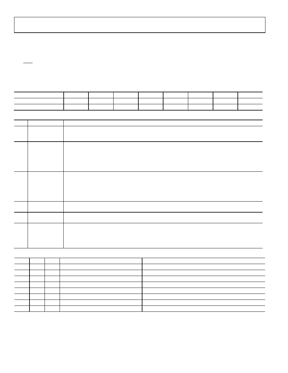
Mode Register
8 Bits, Read/Write Register, Address 38h, 3Ah, Default Value 00h
The mode register configures the part and determines its operating mode. Writing to the mode register clears the ADC status register, sets
the RDY pin to a logic high level, exits all current operations, and starts the mode specified by the mode bits.
The AD7732 contains only one mode register. Bit 1 of the address is used for writing to the mode register to specify the channel selected
for the operation determined by the MD2 to MD0 bits. Only the address 38h must be used for reading from the mode register.
Bit
Bit 7
Bit 6
Bit 5
Bit 4
Bit 3
Bit 2
Bit 1
Bit 0
Mnemonic
MD2
MD1
MD0
CLKDIS
DUMP
Cont RD
24/16 BIT
CLAMP
Default
0
Bit
Mnemonic
Description
7–5
MD2–MD0
Mode Bits. These three bits determine the AD7732 operation mode. Writing a new value to the mode bits will
exit the part from the mode in which it has been operating and place it in the newly requested mode
immediately. The function of the mode bits is described in more detail below.
4
CLKDIS
Master Clock Output Disable. When this bit is set to 1, the master clock is disabled from appearing at the
MCLKOUT pin and the MCLKOUT pin is in a high impedance state. This allows turning off the MCLKOUT as a
power saving feature. When using an external clock on MCLKIN, the AD7732 continues to have internal clocks
and will convert normally regardless of the CLKDIS bit state. When using a crystal oscillator or ceramic
resonator across the MCLKIN and MCLKOUT pins, the AD7732 clock is stopped and no conversions can take
place when the CLKDIS bit is active. The AD7732 digital interface can still be accessed using the SCLK pin.
3
DUMP
DUMP Mode. When this bit is reset to 0, the channel status register and channel data register will be
addressed and read separately. When the DUMP bit is set to 1, the channel status register will be followed
immediately by a read of the channel data register regardless of whether the status or data register has been
addressed through the communication register. The continuous read mode will always be dump mode
reading of the channel status and data register, regardless of the dump bit value (see the Digital Interface
Description section for more details).
2
Cont RD
When this bit is set to 1, the AD7732 will operate in the continuous read mode (see the Digital Interface
Description section for more details).
1
24/16 BIT
The Channel Data Register Data Width Selection Bit. When set to 1, the channel data registers will be 24 bits
wide. When set to 0, the channel data registers will be 16 bits wide.
0
CLAMP
This bit determines the channel data register’s value when the analog input voltage is outside the nominal
input voltage range. When the CLAMP bit is set to 1, the channel data register will be digitally clamped either
to all 0s or all 1s when the analog input voltage goes outside the nominal input voltage range. When the
CLAMP bit is reset to 0, the data registers reflect the analog input voltage even outside the nominal voltage
range (see the Analog Input’s Extended Voltage Range section).
MD2
MD1
MD0
Mode
Address Used for Mode Register Write Specifies:
0
Idle Mode
0
1
Continuous Conversion Mode
The First Channel to Start Converting
0
1
0
Single Conversion Mode
Channel to Convert
0
1
Power-Down (Standby) Mode
1
0
ADC Zero-Scale Self-Calibration
Channel Conversion Time Used for the ADC Self-Calibration
1
0
1
For Future Use
1
0
Channel Zero-Scale System Calibration
Channel to Calibrate
1
Channel Full-Scale System Calibration
Channel to Calibrate
相关PDF资料 |
PDF描述 |
|---|---|
| VE-B2M-EY | CONVERTER MOD DC/DC 10V 50W |
| EVAL-AD7793EBZ | BOARD EVALUATION FOR AD7793 |
| RCM15DCBD-S189 | CONN EDGECARD 30POS R/A .156 SLD |
| 0982660775 | CBL 9POS 0.5MM JMPR TYPE A 5" |
| EVAL-AD7734EBZ | BOARD EVALUATION FOR AD7734 |
相关代理商/技术参数 |
参数描述 |
|---|---|
| EVAL-AD7734EBZ | 功能描述:BOARD EVALUATION FOR AD7734 RoHS:是 类别:编程器,开发系统 >> 评估板 - 模数转换器 (ADC) 系列:- 产品培训模块:Obsolescence Mitigation Program 标准包装:1 系列:- ADC 的数量:1 位数:12 采样率(每秒):94.4k 数据接口:USB 输入范围:±VREF/2 在以下条件下的电源(标准):- 工作温度:-40°C ~ 85°C 已用 IC / 零件:MAX11645 已供物品:板,软件 |
| EVAL-AD7738EB | 制造商:Analog Devices 功能描述:Evaluation Board For AD7738 ADC 制造商:Analog Devices 功能描述:EVALUATION BOARD I.C. - Bulk |
| EVAL-AD7738EBZ | 功能描述:BOARD EVAL FOR AD7738 RoHS:是 类别:编程器,开发系统 >> 评估板 - 模数转换器 (ADC) 系列:- 产品培训模块:Obsolescence Mitigation Program 标准包装:1 系列:- ADC 的数量:1 位数:12 采样率(每秒):94.4k 数据接口:USB 输入范围:±VREF/2 在以下条件下的电源(标准):- 工作温度:-40°C ~ 85°C 已用 IC / 零件:MAX11645 已供物品:板,软件 |
| EVAL-AD7739EB | 制造商:Analog Devices 功能描述:EVALUATION BOARD I.C. - Bulk |
| EVAL-AD7739EBZ | 功能描述:BOARD EVAL FOR AD7739 RoHS:是 类别:编程器,开发系统 >> 评估板 - 模数转换器 (ADC) 系列:- 产品培训模块:Obsolescence Mitigation Program 标准包装:1 系列:- ADC 的数量:1 位数:12 采样率(每秒):94.4k 数据接口:USB 输入范围:±VREF/2 在以下条件下的电源(标准):- 工作温度:-40°C ~ 85°C 已用 IC / 零件:MAX11645 已供物品:板,软件 |
发布紧急采购,3分钟左右您将得到回复。