- 您现在的位置:买卖IC网 > PDF目录16575 > EVAL-ADM2487EEB5Z (Analog Devices Inc)BOARD EVAL FOR ADM2487 PDF资料下载
参数资料
| 型号: | EVAL-ADM2487EEB5Z |
| 厂商: | Analog Devices Inc |
| 文件页数: | 7/20页 |
| 文件大小: | 0K |
| 描述: | BOARD EVAL FOR ADM2487 |
| 标准包装: | 1 |
| 主要目的: | 接口,收发器,RS-485 |
| 已用 IC / 零件: | ADM2487 |
| 已供物品: | 板 |
ADM2482E/ADM2487E
Rev. A | Page 15 of 20
THERMAL SHUTDOWN
The ADM2482E/ADM2487E contain thermal shutdown
circuitry that protects the parts from excessive power dissipa-
tion during fault conditions. Shorting the driver outputs to a
low impedance source can result in high driver currents. The
thermal sensing circuitry detects the increase in die temperature
under this condition and disables the driver outputs. This
circuitry is designed to disable the driver outputs when a die
temperature of 150°C is reached. As the device cools, the drivers
are re-enabled at a temperature of 140°C.
TRUE FAIL-SAFE RECEIVER INPUTS
The receiver inputs have a true fail-safe feature that ensures
that the receiver output is high when the inputs are open or
shorted. During line idle conditions, when no driver on the
bus is enabled, the voltage across a terminating resistance at
the receiver input decays to 0 V. With traditional transceivers,
receiver input thresholds specified between 200 mV and
+200 mV mean that external bias resistors are required on the
A and B pins to ensure that the receiver outputs are in a known
state. The true fail-safe receiver input feature eliminates the
need for bias resistors by specifying the receiver input threshold
between 30 mV and 200 mV. The guaranteed negative thre-
shold means that when the voltage between A and B decays to
0 V, the receiver output is guaranteed to be high.
MAGNETIC FIELD IMMUNITY
The limitation on the magnetic field immunity of the iCoupler
is set by the condition in which an induced voltage in the
receiving coil of the transformer is large enough to either
falsely set or reset the decoder. The following analysis defines
the conditions under which this may occur. The 3 V operating
condition of the ADM2482E/ADM2487E is examined because
it represents the most susceptible mode of operation.
The pulses at the transformer output have an amplitude greater
than 1 V. The decoder has a sensing threshold of about 0.5 V,
thus establishing a 0.5 V margin in which induced voltages can
be tolerated.
The voltage induced across the receiving coil is given by
N
n
r
dt
dβ
V
n
,
2
,
1
;
2
K
=
π
=
∑
where:
β is the magnetic flux density (gauss).
N is the number of turns in the receiving coil.
rn is the radius of the nth turn in the receiving coil (cm).
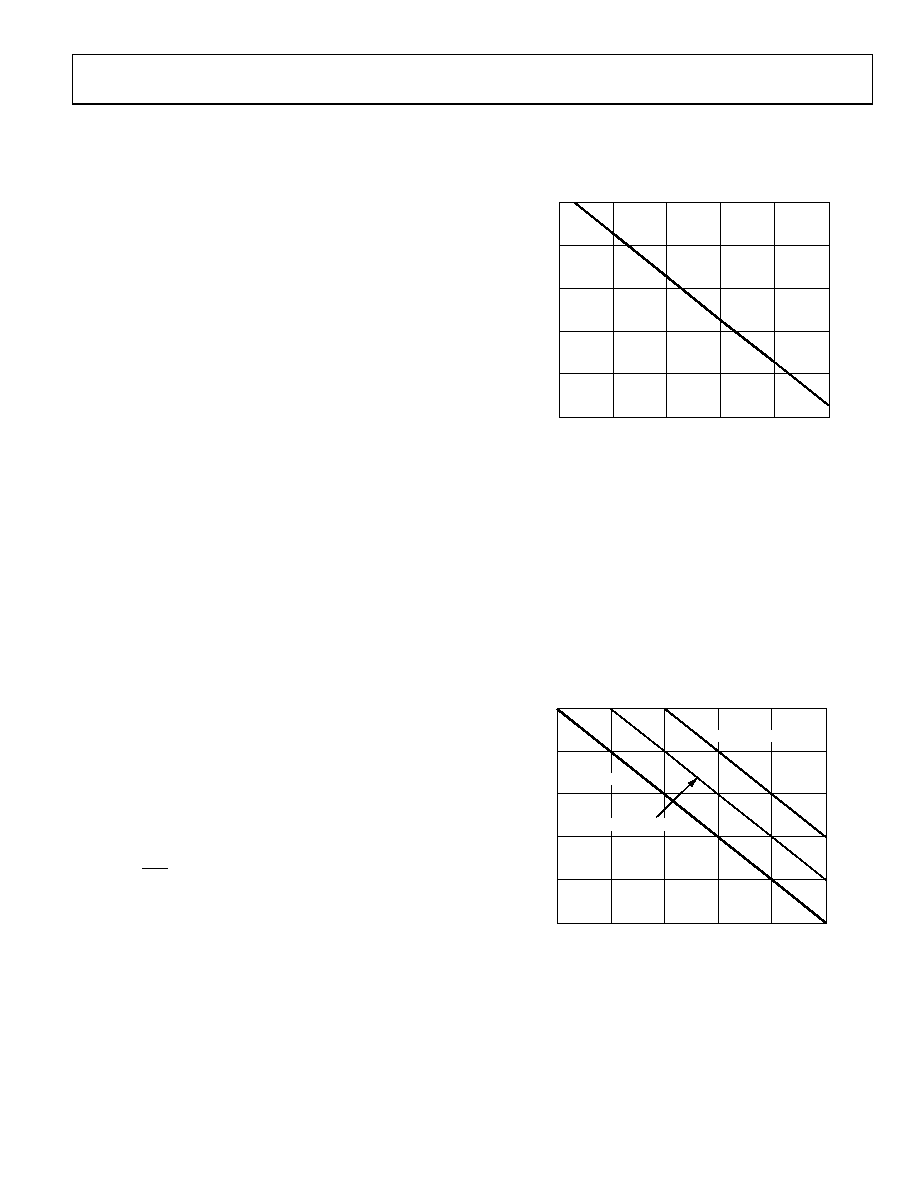
Given the geometry of the receiving coil and an imposed
requirement that the induced voltage is, at most, 50% of the
0.5 V margin at the decoder, a maximum allowable magnetic
field can be determined using Figure 31.
MAGNETIC FIELD FREQUENCY (Hz)
1k
10k
100k
100M
1M
10M
100
10
1
0.1
0.01
0.001
M
A
XI
M
U
M
A
L
O
W
A
B
L
E
MA
G
N
ET
IC
F
L
U
X
DE
NS
IT
Y
(
kG
AUS
S
)
07
37
9-
0
23
Figure 31. Maximum Allowable External Magnetic Flux Density
For example, at a magnetic field frequency of 1 MHz, the
maximum allowable magnetic field of 0.2 kgauss induces a
voltage of 0.25 V at the receiving coil. This is about 50% of the
sensing threshold and does not cause a faulty output transition.
Similarly, if such an event occurs during a transmitted pulse and
is the worst-case polarity, it reduces the received pulse from
>1.0 V to 0.75 V, still well above the 0.5 V sensing threshold
of the decoder.
Figure 32 shows the magnetic flux density values in terms of
more familiar quantities, such as maximum allowable current
flow at given distances away from the ADM2482E/ADM2487E
transformers.
MAGNETIC FIELD FREQUENCY (Hz)
1k
10k
100k
100M
1M
10M
DISTANCE = 1m
DISTANCE = 100mm
DISTANCE = 5mm
1000
100
0.1
1
10
0.01
M
AX
IM
U
M
AL
L
O
W
A
BL
E
CURR
E
NT
(
kA)
07
37
9-
02
4
Figure 32. Maximum Allowable Current for
Various Current-to-ADM2482E/ADM2487E Spacings
With combinations of strong magnetic field and high frequency,
any loops formed by PCB traces can induce error voltages large
enough to trigger the thresholds of succeeding circuitry.
Care should be taken in the layout of such traces to avoid this
possibility.
相关PDF资料 |
PDF描述 |
|---|---|
| ESA10DTKT-S288 | CONN EDGECARD 20POS .125 EXTEND |
| EMA10DTKT-S288 | CONN EDGECARD 20POS .125 EXTEND |
| EBM08DRSN-S273 | CONN EDGECARD 16POS DIP .156 SLD |
| EBM08DRSD-S273 | CONN EDGECARD 16POS DIP .156 SLD |
| GMM11DSEN-S243 | CONN EDGECARD 22POS .156 EYELET |
相关代理商/技术参数 |
参数描述 |
|---|---|
| EVAL-ADM2490EEBZ | 功能描述:BOARD EVAL FOR ADM2490 RoHS:是 类别:编程器,开发系统 >> 评估演示板和套件 系列:* 标准包装:1 系列:- 主要目的:电信,线路接口单元(LIU) 嵌入式:- 已用 IC / 零件:IDT82V2081 主要属性:T1/J1/E1 LIU 次要属性:- 已供物品:板,电源,线缆,CD 其它名称:82EBV2081 |
| EVAL-ADM2491EEBZ | 功能描述:BOARD EVAL FOR ADM2491 RoHS:是 类别:编程器,开发系统 >> 评估演示板和套件 系列:- 标准包装:1 系列:- 主要目的:数字电位器 嵌入式:- 已用 IC / 零件:AD5258 主要属性:- 次要属性:- 已供物品:板 相关产品:AD5258BRMZ1-ND - IC POT DGTL I2C1K 64P 10MSOPAD5258BRMZ10-ND - IC POT DGTL I2C 10K 64P 10MSOPAD5258BRMZ100-ND - IC POT DGTL I2C 100K 64P 10MSOPAD5258BRMZ50-ND - IC POT DGTL I2C 50K 64P 10MSOPAD5258BRMZ1-R7-ND - IC POT DGTL I2C 1K 64P 10MSOPAD5258BRMZ10-R7-ND - IC POT DGTL I2C 10K 64P 10MSOPAD5258BRMZ50-R7-ND - IC POT DGTL I2C 50K 64P 10MSOPAD5258BRMZ100-R7-ND - IC POT DGTL I2C 100K 64P 10MSOP |
| EVAL-ADM2582EEB1Z | 功能描述:BOARD EVAL FOR ADM2582E RoHS:否 类别:编程器,开发系统 >> 评估演示板和套件 系列:* 标准包装:1 系列:- 主要目的:电信,线路接口单元(LIU) 嵌入式:- 已用 IC / 零件:IDT82V2081 主要属性:T1/J1/E1 LIU 次要属性:- 已供物品:板,电源,线缆,CD 其它名称:82EBV2081 |
| EVAL-ADM2582EEBZ | 功能描述:BOARD EVAL FOR ADM2582 RoHS:是 类别:编程器,开发系统 >> 评估演示板和套件 系列:isoPower® 标准包装:1 系列:- 主要目的:数字电位器 嵌入式:- 已用 IC / 零件:AD5258 主要属性:- 次要属性:- 已供物品:板 相关产品:AD5258BRMZ1-ND - IC POT DGTL I2C1K 64P 10MSOPAD5258BRMZ10-ND - IC POT DGTL I2C 10K 64P 10MSOPAD5258BRMZ100-ND - IC POT DGTL I2C 100K 64P 10MSOPAD5258BRMZ50-ND - IC POT DGTL I2C 50K 64P 10MSOPAD5258BRMZ1-R7-ND - IC POT DGTL I2C 1K 64P 10MSOPAD5258BRMZ10-R7-ND - IC POT DGTL I2C 10K 64P 10MSOPAD5258BRMZ50-R7-ND - IC POT DGTL I2C 50K 64P 10MSOPAD5258BRMZ100-R7-ND - IC POT DGTL I2C 100K 64P 10MSOP |
| EVAL-ADM2587EEB1Z | 功能描述:界面开发工具 Low EMI 4-layer board for ADM258E RoHS:否 制造商:Bourns 产品:Evaluation Boards 类型:RS-485 工具用于评估:ADM3485E 接口类型:RS-485 工作电源电压:3.3 V |
发布紧急采购,3分钟左右您将得到回复。