- 您现在的位置:买卖IC网 > PDF目录16231 > EVAL-ADM3251EEBZ (Analog Devices Inc)BOARD EVALUATION ADM3251 PDF资料下载
参数资料
| 型号: | EVAL-ADM3251EEBZ |
| 厂商: | Analog Devices Inc |
| 文件页数: | 6/16页 |
| 文件大小: | 0K |
| 描述: | BOARD EVALUATION ADM3251 |
| 产品培训模块: | Fully Isolated ADM3251E RS-232 Transceiver |
| 标准包装: | 1 |
| 系列: | isoPower® |
| 主要目的: | 接口,隔离式,RS-232 |
| 嵌入式: | 否 |
| 已用 IC / 零件: | ADM3251E |
| 主要属性: | 2.5 kV 隔离式(电源和数据)RS-232 收发器,隔离式 DC/DC 转换器 |
| 已供物品: | 板,IC 样品 |
| 产品目录页面: | 790 (CN2011-ZH PDF) |
| 相关产品: | ADM3251EARWZ-ND - IC TXRX RS232 ISOLATED 20-SOIC ADM3251EARWZ-REELDKR-ND - IC LINE DVR/RCVR RS232 20-SOIC ADM3251EARWZ-REELCT-ND - IC LINE DVR/RCVR RS232 20-SOIC ADM3251EARWZ-REELTR-ND - IC LINE DVR/RCVR RS232 20-SOIC |
ADM3251E
Data Sheet
The limitation on the ADM3251E magnetic field immunity is
set by the condition in which induced voltage in the receiving
coil of the transformer is sufficiently large to falsely set or reset
the decoder. The following analysis defines the conditions
under which this can occur.
The pulses at the transformer output have an amplitude of >1.0 V.
The decoder has a sensing threshold of about 0.5 V, thus estab-
lishing a 0.5 V margin in which induced voltages can be tolerated.
The voltage induced across the receiving coil is given by
V = (dβ/dt)Σπrn2; n = 1, 2, … , N
where:
β is the magnetic flux density (gauss).
N is the number of turns in the receiving coil.
rn is the radius of the nth turn in the receiving coil (cm).
Given the geometry of the receiving coil internally and an
imposed requirement that the induced voltage be, at most, 50%
of the 0.5 V margin at the decoder, a maximum allowable
magnetic field is calculated, as shown in Figure 22.
MAGNETIC FIELD FREQUENCY (Hz)
100
M
A
X
IM
U
M
A
LLOWA
B
LE
M
A
GN
E
TIC
FLU
X
DE
NS
IT
Y
(
kg
au
ss)
0.001
1M
10
0.01
1k
10k
10M
0.1
1
100M
100k
07388-
200
Figure 22. Maximum Allowable External Magnetic Flux Density
For example, at a magnetic field frequency of 1 MHz, the
maximum allowable magnetic field of 0.2 kgauss induces a
voltage of 0.25 V at the receiving coil. This is approximately
50% of the sensing threshold and does not cause a faulty output
transition. Similarly, if such an event occurs during a transmitted
pulse (and is of the worst-case polarity), the received pulse is
reduced from >1.0 V to 0.75 V, which is still well above the
0.5 V sensing threshold of the decoder.
The preceding magnetic flux density values correspond to
specific current magnitudes at given distances from the trans-
formers. Figure 23 expresses these allowable current
magnitudes as a function of frequency for selected distances. As
shown in Figure 23, the ADM3251E is extremely immune and
can be affected only by extremely large currents operated at
high frequency very close to the component. For example, at a
magnetic field frequency of 1 MHz, a 0.5 kA current placed
5 mm away from the ADM3251E is required to affect the
operation of the component.
MAGNETIC FIELD FREQUENCY (Hz)
M
AX
IM
UM
AL
L
O
W
ABL
E
CURRE
NT
(
kA)
1k
100
10
1
0.1
0.01
1k
10k
100M
100k
1M
10M
DISTANCE = 5mm
DISTANCE = 1m
DISTANCE = 100mm
07388-
201
Figure 23. Maximum Allowable Current for Various Current-to-ADM3251E
Spacings
In the presence of strong magnetic fields and high frequencies,
any loops formed by PCB traces may induce error voltages
sufficiently large to trigger the thresholds of succeeding
circuitry. Exercise care in the layout of such traces to avoid this
possibility.
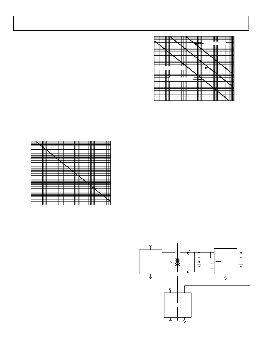
ISOLATED POWER SUPPLY CIRCUIT
To operate the ADM3251E with its internal dc-to-dc converter
disabled, connect a voltage of between 3.0 V and 3.7 V to the
VCC pin and apply an isolated power of between 3.0 V and 5.5 V
to the VISO pin, referenced to GNDISO.
A transformer driver circuit with a center-tapped transformer
and LDO can be used to generate the isolated supply, as shown
in Figure 24. The center-tapped transformer provides electrical
isolation of the 5 V power supply. The primary winding of the
transformer is excited with a pair of square waveforms that are
180° out of phase with each other. A pair of Schottky diodes and
a smoothing capacitor are used to create a rectified signal from
the secondary winding. The ADP3330 linear voltage regulator
provides a regulated power supply to the bus side circuitry
ADP3330
IN
NR
+
SD103C
22F
10F
5V
OUT
SD103C
78253
VCC
GND
ISOLATION
BARRIER
SD
ERR
TRANSFORMER
DRIVER
VCC
GND
VISO
GNDISO
ADM3251E
07388-
022
Figure 24. Isolated Power Supply Circuit
Rev. G | Page 14 of 16
相关PDF资料 |
PDF描述 |
|---|---|
| BQ2002EPN | IC CONTROLLER FASTCHRGE 8-DIP |
| BQ2057DGK | IC LI-ION LDO CHRG MGMT 8-MSOP |
| EVAL-AD5934EBZ | BOARD EVALUATION FOR AD5934 |
| BQ2057CDGK | IC LI-ION LDO CHRG MGMT 8-MSOP |
| VE-J7Y-EZ-F3 | CONVERTER MOD DC/DC 3.3V 16.5W |
相关代理商/技术参数 |
参数描述 |
|---|---|
| EVAL-ADM3252EEBZ | 功能描述:BOARD EVAL FOR ADM3252E RoHS:是 类别:编程器,开发系统 >> 评估演示板和套件 系列:- 标准包装:1 系列:- 主要目的:电信,线路接口单元(LIU) 嵌入式:- 已用 IC / 零件:IDT82V2081 主要属性:T1/J1/E1 LIU 次要属性:- 已供物品:板,电源,线缆,CD 其它名称:82EBV2081 |
| EVAL-ADM4168EEBZ | 功能描述:界面开发工具 EVALUATION BOARD RoHS:否 制造商:Bourns 产品:Evaluation Boards 类型:RS-485 工具用于评估:ADM3485E 接口类型:RS-485 工作电源电压:3.3 V |
| EVAL-ADM8830EB | 制造商:Analog Devices 功能描述:EVALUATION BOARD I.C. - Bulk |
| EVAL-ADM8843EB | 制造商:Analog Devices 功能描述:EVALUATION BOARD I.C. - Bulk |
| EVAL-ADM8845EB | 制造商:AD 制造商全称:Analog Devices 功能描述:Charge Pump Driver for LCD White LED Backlights |
发布紧急采购,3分钟左右您将得到回复。