- 您现在的位置:买卖IC网 > PDF目录17302 > F910J227KNC (Nichicon)CAP TANT 220UF 6.3V 10% 2917 PDF资料下载
参数资料
| 型号: | F910J227KNC |
| 厂商: | Nichicon |
| 文件页数: | 1/1页 |
| 文件大小: | 0K |
| 描述: | CAP TANT 220UF 6.3V 10% 2917 |
| 标准包装: | 500 |
| 系列: | F91 |
| 电容: | 220µF |
| 电压 - 额定: | 6.3V |
| 容差: | ±10% |
| ESR(等效串联电阻): | 100 毫欧 |
| 类型: | 模制 |
| 工作温度: | -55°C ~ 125°C |
| 安装类型: | 表面贴装 |
| 封装/外壳: | 2917(7343 公制) |
| 尺寸/尺寸: | 0.287" L x 0.169" W(7.30mm x 4.30mm) |
| 高度 - 座高(最大): | 0.118"(3.00mm) |
| 制造商尺寸代码: | N |
| 特点: | 通用 |
| 包装: | 带卷 (TR) |
�� �
�
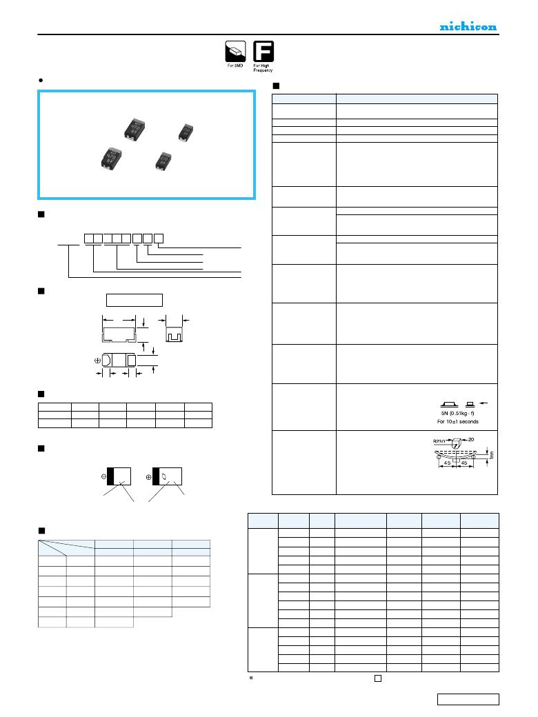
�SOLID� TANTALUM� ELECTROLYTIC� CAPACITORS�
�F91�
�LOW� ESR�
�Resin-molded� Chip�
�Compliant� to� the� RoHS� directive� (2002/95/EC).�
�Specifications�
�Item�
�Category�
�Temperature� Range�
�Capacitance� Tolerance�
�Dissipation� Factor� (120Hz)�
�ESR� (100kHz)�
�Leakage� Current�
�Capacitance� Change�
�by� Temperature�
�Performance� Characteristics�
�--55� to� +125� ?� C� (Rated� temperature� :� +� 85� ?� C� )�
�±� 20%,� ±10%� (at� 120Hz)�
�Refer� to� the� table� below.�
�Refer� to� the� table� below.�
�?� After� 1� minute's� application� of� rated� voltage,� leakage� current�
�at� 20� ?� C� is� not� more� than� 0.01CV� or� 0.5μA,� whichever� is� greater.�
�?� After� 1� minute's� application� of� rated� voltage,� leakage� current�
�at� 85� ?� C� is� not� more� than� 0.1CV� or� 5μA,� whichever� is� greater.�
�?� After� 1� minute's� application� of� derated� voltage,� leakage� current�
�at� 125� ?� C� is� not� more� than� 0.125CV� or� 6.3μA,� whichever� is� greater.�
�.�
�+15%� Max.� (at� +125� ?� C� )�
�+10%� Max.� (at� +85� ?� C� )�
�--10%� Max.� (at� --55� ?� C� )�
�Type� numbering� system� (Example� :� 10V� 100μF)�
�Damp� Heat�
�(Steady� State)�
�At� 40� ?� C� 90� to� 95%� R.H.� 500� hours� (No� voltage� applied)�
�Capacitance� Change� Within� ±10%� of� the� initial� value�
�Dissipation� Factor......Initial� specified� value� or� less�
�1�
�2�
�3�
�4�
�5�
�6�
�7�
�8�
�9�
�10�
�11�
�Leakage� Current........Initial� specified� value� or� less�
�F� 9� 1� 1� A� 1� 0� 7� M� C�
���Case� code�
�Capacitance� tolerance�
�Rated� capacitance�
�Rated� voltage�
�Temperature� Cycles�
�--55� ?� C� /� +125� ?� C� 30� minutes� each� 5� cycles�
�Capacitance� Change� Within� ±5%� of� the� initial� value�
�Dissipation� Factor......Initial� specified� value� or� less�
�Leakage� Current........Initial� specified� value� or� less�
�10� seconds� reflow� at� 260� ?� C,�
�Drawing�
�C� ?� N� Case�
�Series�
�Resistance�
�to� Soldering� Heat�
�5� seconds� immersion� at� 260� ?� C�
�Capacitance� Change� Within� ±5%� of� the� initial� value�
�Dissipation� Factor......Initial� specified� value� or� less�
�Leakage� Current........Initial� specified� value� or� less�
�After� application� of� surge� in� series� with� a� 33� ?� resistor� at� the� rate� of� 30�
�seconds� ON,� 30� seconds� OFF,� for� 1000� sucessive� test� cycles� at� 85� ?� C,�
�L�
�H�
�W� 1�
�Surge� ?�
�capacitors� shall� meet� the� characteristic� requirements� table� below.�
�Capacitance� Change� ....� Within� ±5%� of� the� initial� value�
�Dissipation� Factor� ........� Initial� specified� value� or� less�
�Leakage� Current� ..........� Initial� specified� value� or� less�
�After� 2000� hours'� application� of� rated� voltage� in� series� with� a� 3� ?� resistor�
�at� 85� ?� C� ,� or� derated� voltage� in� series� with� a� 3� ?� resistor� at� 125� ?� C� ,�
�W� 2�
�Endurance� ?�
�capacitors� shall� meet� the� characteristics� requirements� table� below.�
�Capacitance� Change� ......� Within� ±10� %� of� the� initial� value�
�S�
�S�
�Dissipation� Factor� ..........� Initial� specified� value� or� less�
�Leakage� Current� ............� Initial� specified� value� or� less�
�Dimensions�
�Case� Code� L�
�C� 6.0� ±� 0.2�
�N� 7.3� ±� 0.2�
�W� 1�
�3.2� ±� 0.2�
�4.3� ±� 0.2�
�W� 2�
�2.2� ±� 0.1�
�2.4� ±� 0.1�
�H�
�2.5� ±� 0.2�
�2.8� ±� 0.2�
�(mm)�
�S�
�1.3� ±� 0.2�
�1.3� ±� 0.2�
�Shear� Test�
�After� applying� the� pressure� load� of� 5N� for� 10±1� seconds�
�horizontally� to� the� center� of� capacitor� side� body� which� has� no�
�electrode� and� has� been� soldered�
�beforehand� on� a� substrate,� there� shall�
�be� found� neither� exfoliation� nor� its� sign�
�at� the� terminal� electrode.�
�Keeping� a� capacitor� surface-�
�mounted� on� a� substrate� upside� down�
�Marking�
�and� supporting� the� substrate� at� both�
�of� the� opposite� bottom� points� 45mm�
�C� Case�
�N� Case�
�Terminal� Strength�
�apart� from� the� center� of� capacitor,�
�the� pressure� strength� is� applied� with�
�a� specified� jig� at� the� center� of�
�substrate� so� that� the� substrate� may� bend� by� 1mm� as� illustrated.�
�Then,� there� shall� be� found� no� remarkable� abnormality� on� the�
�capacitor� terminals.�
�Rated� voltage� (V)�
�Rated� Capacitance� (� μ� F)�
�Rated� voltage� (V)�
�?� As� for� the� surge� and� derated� voltage� at� 125� ?� C� ,� refer� to� page� 332� for� details.�
�Standard� Ratings�
�Rated� Volt�
�Rated�
�Capacitance�
�(μF)�
�150�
�Case�
�code�
�C�
�Part� Number�
�F910G157MCC�
�Leakage�
�Current�
�(μA)�
�6.0�
�Disspation�
�Factor�
�(%� @120Hz)�
�12�
�ESR�
�(m� ?� @100kHz)�
�250�
�Cap.�
�(μF)�
�Code�
�V�
�4�
�0G�
�6.3�
�0J�
�10�
�1A�
�4V�
�220�
�330�
�C�
�N�
�F910G227MCC�
�F910G337MNC�
�8.8�
�13.2�
�12�
�10�
�250�
�100�
�0� 68�
�686�
�C�
�470�
�N�
�F910G477MNC�
�18.8�
�16�
�100�
�100�
�107�
�C�
�C�
�680�
�N�
�F910G687MNC�
�27.2�
�18�
�100�
�150�
�157�
�C�
�C�
�N�
�100�
�C�
�F910J107MCC�
�6.3�
�8�
�250�
�220�
�330�
�470�
�227�
�337�
�477�
�C�
�N�
�N�
�C� ?� N�
�N�
�N�
�N�
�N�
�6.3V�
�150�
�220�
�220�
�330�
�C�
�C�
�N�
�N�
�F910J157MCC�
�F910J227MCC�
�F910J227MNC�
�F910J337MNC�
�9.5�
�13.9�
�13.9�
�20.8�
�12�
�14�
�10�
�14�
�250�
�250�
�100�
�100�
�680�
�687�
�N�
�470�
�N�
�F910J477MNC�
�29.6�
�16�
�100�
�68�
�100�
�C�
�C�
�F911A686MCC�
�F911A107MCC�
�6.8�
�10.0�
�8�
�10�
�300�
�250�
�10V�
�150�
�220�
�330�
�N�
�N�
�N�
�F911A157MNC�
�F911A227MNC�
�F911A337MNC�
�15.0�
�22.0�
�33.0�
�10�
�12�
�18�
�100�
�100�
�100�
�In� case� of� capacitance� tolerance�
�system.�
�±� 10%� type,� K� will� be� put� at� 9th� digit� of� type� numbering�
�CAT.8100B�
�相关PDF资料 |
PDF描述 |
|---|---|
| IR2127SPBF | IC MOSFET DRVR CURR SENSE 8SOIC |
| IR21364STRPBF | IC DRIVER BRIDGE 3PHASE 28-SOIC |
| IRS2336DSTRPBF | IC GATE DRIVER HV 3PHASE 28-SOIC |
| IR2118SPBF | IC MOSFET DRIVER HIGH SIDE 8SOIC |
| IRS2336DMTRPBF | IC GATE DRIVER HV 3PHASE 48-MLPQ |
相关代理商/技术参数 |
参数描述 |
|---|---|
| F910J227MCC | 功能描述:钽质电容器-固体SMD 6.3volts 220uF 6x3.2 RoHS:否 制造商:AVX 电容:100 uF 电压额定值:20 V ESR: 容差:10 % 外壳代码 - in:2917 外壳代码 - mm:7343 高度:4.1 mm 制造商库存号:E Case 工作温度范围:- 55 C to + 125 C 系列:TBM 产品:Tantalum Solid Low ESR Commercial Grade 封装:Bulk |
| F910J227MNC | 功能描述:钽质电容器-固体SMD 6.3volts 220uF 7.3x4.3 RoHS:否 制造商:AVX 电容:100 uF 电压额定值:20 V ESR: 容差:10 % 外壳代码 - in:2917 外壳代码 - mm:7343 高度:4.1 mm 制造商库存号:E Case 工作温度范围:- 55 C to + 125 C 系列:TBM 产品:Tantalum Solid Low ESR Commercial Grade 封装:Bulk |
| F910J337KNC | 功能描述:钽质电容器-固体SMD 330uF 6.3V 10% RoHS:否 制造商:AVX 电容:100 uF 电压额定值:20 V ESR: 容差:10 % 外壳代码 - in:2917 外壳代码 - mm:7343 高度:4.1 mm 制造商库存号:E Case 工作温度范围:- 55 C to + 125 C 系列:TBM 产品:Tantalum Solid Low ESR Commercial Grade 封装:Bulk |
| F910J337MNC | 功能描述:钽质电容器-固体SMD 6.3volts 330uF 7.3x4.3 RoHS:否 制造商:AVX 电容:100 uF 电压额定值:20 V ESR: 容差:10 % 外壳代码 - in:2917 外壳代码 - mm:7343 高度:4.1 mm 制造商库存号:E Case 工作温度范围:- 55 C to + 125 C 系列:TBM 产品:Tantalum Solid Low ESR Commercial Grade 封装:Bulk |
| F910J477KNC | 功能描述:钽质电容器-固体SMD 470uF 6.3V 10% RoHS:否 制造商:AVX 电容:100 uF 电压额定值:20 V ESR: 容差:10 % 外壳代码 - in:2917 外壳代码 - mm:7343 高度:4.1 mm 制造商库存号:E Case 工作温度范围:- 55 C to + 125 C 系列:TBM 产品:Tantalum Solid Low ESR Commercial Grade 封装:Bulk |
发布紧急采购,3分钟左右您将得到回复。