- 您现在的位置:买卖IC网 > PDF目录17404 > F971A686MNC (Nichicon)CAP TANT 68UF 10V 20% SMD PDF资料下载
参数资料
| 型号: | F971A686MNC |
| 厂商: | Nichicon |
| 文件页数: | 1/2页 |
| 文件大小: | 0K |
| 描述: | CAP TANT 68UF 10V 20% SMD |
| 产品培训模块: | Nichicon Tantalum Cap Overview |
| 产品目录绘图: | F9(1,2,3,7) Series Bottom F9(1,2,3,7) Series Side |
| 标准包装: | 1 |
| 系列: | F97 |
| 电容: | 68µF |
| 电压 - 额定: | 10V |
| 容差: | ±20% |
| 类型: | 模制 |
| 工作温度: | -55°C ~ 125°C |
| 安装类型: | 表面贴装 |
| 封装/外壳: | 2917(7343 公制) |
| 尺寸/尺寸: | 0.287" L x 0.169" W(7.30mm x 4.30mm) |
| 高度 - 座高(最大): | 0.118"(3.00mm) |
| 制造商尺寸代码: | N |
| 特点: | 高可靠性 |
| 包装: | 标准包装 |
| 其它名称: | 493-5829-6 |
�� �
�
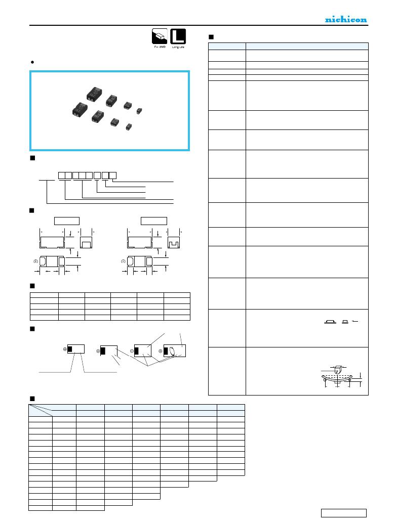
�SOLID� TANTALUM� ELECTROLYTIC� CAPACITORS�
�F97�
�--55� to� +125� ?� C� (Rated� temperature� :� 85� ?� C� .)�
�Resin-molded� Chip,�
�High� Reliability�
�(High� temperature� /�
�moisture� resistance)� Series�
�Compliant� to� the� RoHS� directive� (2002/95/EC).�
�Specifications�
�Item� Performance� Characteristics�
�Category�
�Temperature� Range�
�Capacitance� Tolerance� ±� 20%,� ±� 10%� (at� 120Hz)�
�Dissipation� Factor�
�ESR� (100kHz)�
�Leakage� Current� ?�
�Capacitance� Change�
�by� Temperature�
�Damp� Heat�
�(Steady� State)�
�Refer� to� next� page�
�Refer� to� next� page�
�?� After� 1� minute'� s� application� of� rated� voltage,leakage� current� at� 20� ?� C�
�is� not� more� than� 0.01CV� or� 0.5� μA,� whichever� is� greater.�
�?� After� 1� minute'� s� application� of� rated� voltage,leakage� current� at� 85� ?� C�
�is� not� more� than� 0.1CV� or� 5μA,whichever� is� greater.�
�?� After� 1� minute'� s� application� of� derated� voltage,leakage� current� at�
�125� ?� C� is� not� more� than� 0.125CV� or� 6.3� μA,whichever� is� greater.�
�+15%� Max.� (at� +125� ?� C� )�
�+10%� Max.� (at� +85� ?� C� )�
�--10%� Max.� (at� --55� ?� C� )�
�At� 85� ?� C� ,� 85%� R.H.,For� 1000� hours� (No� voltage� applied)�
�Capacitance� Change� ?� ?� ?� ?� ?� ?� Within� ±10%� of� the� initial� value�
�Dissipation� Factor� ?� ?� ?� ?� ?� ?� ?� ?� ?� ?� ?� Initial� specified� value� or� less�
�Leakage� Current� ?� ?� ?� ?� ?� ?� ?� ?� ?� ?� ?� ?� 125%� or� less� than� the� initial� specified� value�
�Type� numbering� system� (Example� :� 16V� 3.3μF)�
�1� 2� 3� 4� 5� 6� 7� 8� 9� 10� 11�
�Load� Humidity�
�After� 500� hour'� s� application� of� rated� voltage� in� series� with� a� 33� ?�
�resistor� at� 60� ?� C� ,� 90� to� 95%� R.H.,capacitors� meet� the� characteristics�
�requirements� listed� below.�
�Capacitance� Change� ?� ?� ?� ?� ?� ?� Within� ±10%� of� the� initial� value�
�Dissipation� Factor� ?� ?� ?� ?� ?� ?� ?� ?� ?� ?� Initial� specified� value� or� less�
�Rated� voltage�
�F� 9� 7� 1� C� 3� 3� 5� M� B�
�Drawing�
�A� ?� B� Case�
���Case� code�
�Capacitance� tolerance�
�Rated� capacitance�
�Series�
�C� ?� N� Case�
�Temperature� Cycles�
�Resistance�
�to� Soldering� Heat�
�Leakage� Current� ?� ?� ?� ?� ?� ?� ?� ?� ?� ?� ?� ?� 125%� or� less� than� the� initial� specified� value�
�At� --55� ?� C� /� +125� ?� C� ,For� 30� minutes� each,1000� cycles�
�Capacitance� Change� ?� ?� ?� ?� ?� ?� Within� ±� 5%� of� the� initial� value�
�Dissipation� Factor� ?� ?� ?� ?� ?� ?� ?� ?� ?� ?� ?� Initial� specified� value� or� less�
�Leakage� Current� ?� ?� ?� ?� ?� ?� ?� ?� ?� ?� ?� ?� ?� Initial� specified� value� or� less�
�At� 260� ?� C� ,reflowing� capacitors� for� 10� seconds� Max.�
�Capacitance� Change� ?� ?� ?� ?� ?� ?� Within� ±� 5%� of� the� initial� value�
�Dissipation� Factor� ?� ?� ?� ?� ?� ?� ?� ?� ?� ?� ?� Initial� specified� value� or� less�
�Leakage� Current� ?� ?� ?� ?� ?� ?� ?� ?� ?� ?� ?� ?� ?� Initial� specified� value� or� less�
�L�
�W� 1�
�L�
�W� 1�
�After� immersing� capacitors� completely� into� a� solder� pot� at�
�Solderability�
�245� ?� C� for� 2� to� 3� seconds,more� than� 3/4� of� their� electrode� area�
�H�
�H�
�shall� remain� covered� with� new� solder.�
�After� application� of� surge� in� series� with� a� 33� ?� resistor� at� the�
�rate� of� 30� seconds� ON,� 30� seconds� OFF,for� 1000� successive�
�W� 2�
�W� 2�
�Surge� ?�
�test� cycles� at� 85� ?� C� ,capacitors� meet� the� characteristics�
�requirements� listed� below.�
�Capacitance� Change� ?� ?� ?� ?� ?� ?� Within� ±� 5%� of� the� initial� value�
�S�
�S�
�S�
�S�
�Dissipation� Factor� ?� ?� ?� ?� ?� ?� ?� ?� ?� ?� ?� Initial� specified� value� or� less�
�Leakage� Current� ?� ?� ?� ?� ?� ?� ?� ?� ?� ?� ?� ?� ?� Initial� specified� value� or� less�
�Dimensions�
�Case� code�
�A� 3.2�
�L�
�±� 0.2�
�W� 1�
�1.6� ±� 0.2�
�W� 2�
�1.2� ±� 0.1�
�1.6�
�H�
�±� 0.2�
�(mm)�
�S�
�0.8� ±� 0.2�
�Endurance� ?�
�After� 2000� hours'� application� of� rated� voltage� in� series� with� a�
�3� ?� resistor� at� 85� ?� C� ,or� derated� voltage� in� series� with� a� 3� ?�
�resistor� at� 125� ?� C� ,capacitors� meet� the� characteristic�
�requirements� listed� below.�
�Capacitance� Change� ?� ?� ?� ?� ?� ?� Within� ±10%� of� the� initial� value�
�Dissipation� Factor� ?� ?� ?� ?� ?� ?� ?� ?� ?� ?� ?� Initial� specified� value� or� less�
�B�
�C�
�N�
�3.5�
�6.0�
�7.3�
�±� 0.2�
�±� 0.2�
�±� 0.2�
�2.8�
�3.2�
�4.3�
�±� 0.2�
�±� 0.2�
�±� 0.2�
�2.2�
�2.2�
�2.4�
�±� 0.1�
�±� 0.1�
�±� 0.1�
�1.9�
�2.5�
�2.8�
�±� 0.2�
�±� 0.2�
�±� 0.2�
�0.8� ±� 0.2�
�1.3� ±� 0.2�
�1.3� ±� 0.2�
�Leakage� Current� ?� ?� ?� ?� ?� ?� ?� ?� ?� ?� ?� ?� ?� Initial� specified� value� or� less�
�After� applying� the� pressure� load� of� 5N�
�for� 10� ±� 1� seconds� horizontally� to� the�
�center� of� capacitor� side� body� which�
�Marking�
�A� Case�
�B� Case�
�C� Case�
�Month� code�
�N� Case�
�Shear� Test�
�has� no� electrode� and� has� been� 5N� (0.51kg� ?� f)�
�soldered� beforehand� on� an� aluminum� For� 10� ±� 1� seconds�
�substrate,� there� shall� be� found� neither�
�exfoliation� nor� its� sign� at� the� terminal�
�electrode.�
�C105�
�3.3�
�16r�
�Keeping� a� capacitor� surface-mounted� on� a� substrate� upside�
�down� and� supporting� the� substrate� at� both� of� the� opposite�
�Rated� Capacitance�
�specified� jig� at� the� center� of� the� R230�
�Rated� voltage�
�(Voltage� code)�
�Month� code�
�Rated� Voltage� (V)�
�(Capacitance� code� )� Rated� voltage� (V)� Rated� Capacitance� (� μ� F)�
�Terminal� Strength�
�bottom� points� 45mm� apart� from� the� center� of� the� capacitor,� the�
�pressure� strength� is� applied� with� a�
�20�
�substrate� so� that� the� substrate� may�
�bend� by� 1mm� as� illustrated.�
�Then,� there� shall� be� found� no�
�remarkable� abnormality� on� the�
�capacitor� terminals.�
�45�
�45�
�Standard� ratings�
�?� As� for� the� surge� and� derated� voltage� at� 125� ?� C� ,� refer� to� page� 308� for� details.�
�V�
�6.3�
�10�
�16�
�20�
�25�
�35�
�Cap.(� μ� F)�
�Code�
�0J�
�1A�
�1C�
�1D�
�1E�
�1V�
�0.33�
�334�
�A�
�0.47�
�474�
�A�
�A�
�0.68�
�684�
�A�
�A�
�A�
�1�
�105�
�A�
�A�
�A�
�(A)� ?� B�
�1.5�
�155�
�A�
�A�
�A�
�B�
�(A)� ?� B�
�2.2�
�225�
�A�
�A�
�A�
�A�
�?�
�B�
�(A)� ?� B�
�B�
�3.3�
�335�
�A�
�A�
�A�
�?�
�B�
�B�
�B�
�(B)� ?� C�
�4.7�
�6.8�
�475�
�685�
�A�
�A�
�?�
�B�
�A�
�?�
�B�
�B�
�A�
�?�
�B�
�B�
�A� ?� B�
�(B)� ?� C�
�(B)� ?� C�
�C�
�C�
�(C)� ?� N�
�10�
�106�
�B�
�A�
�?�
�B�
�A� ?� B� ?� C�
�(B)� ?� C�
�C� ?� N�
�N�
�15�
�22�
�33�
�47�
�156�
�226�
�336�
�476�
�B�
�A� ?� B�
�(A)� ?� C�
�B� ?� C�
�C�
�A� ?� B�
�(B)� ?� C� ?� N�
�(C)� ?� N�
�(B)� ?� C�
�B� ?� C� ?� N�
�(B)� ?� (C)� ?� N�
�N�
�N�
�(C)� ?� N�
�(C)� ?� N�
�(� )� The� series� in� parentheses� are� being� developed.�
�Please� contact� to� your� local� Nichicon� sales� office� when� these�
�series� are� being� designed� in� your� application.�
�68�
�100�
�686�
�107�
�N�
�N�
�(N)�
�CAT.8100Y�
�相关PDF资料 |
PDF描述 |
|---|---|
| GMC08DREF-S13 | CONN EDGECARD 16POS .100 EXTEND |
| EEC19DRYS | CONN EDGECARD 38POS DIP .100 SLD |
| TH3D686K010E1000 | CAP TANT 68UF 10V 10% 2917 |
| EBC15DRYN | CONN EDGECARD 30POS DIP .100 SLD |
| IPS6021STRRPBF | IC SWITCH IPS 1CH HI SIDE D2PAK- |
相关代理商/技术参数 |
参数描述 |
|---|---|
| F971C105MAA | 功能描述:钽质电容器-固体SMD 16volts 1uF 3.2x1.6 RoHS:否 制造商:AVX 电容:100 uF 电压额定值:20 V ESR: 容差:10 % 外壳代码 - in:2917 外壳代码 - mm:7343 高度:4.1 mm 制造商库存号:E Case 工作温度范围:- 55 C to + 125 C 系列:TBM 产品:Tantalum Solid Low ESR Commercial Grade 封装:Bulk |
| F971C106KBA | 功能描述:钽质电容器-固体SMD 10UF 16V 10% RoHS:否 制造商:AVX 电容:100 uF 电压额定值:20 V ESR: 容差:10 % 外壳代码 - in:2917 外壳代码 - mm:7343 高度:4.1 mm 制造商库存号:E Case 工作温度范围:- 55 C to + 125 C 系列:TBM 产品:Tantalum Solid Low ESR Commercial Grade 封装:Bulk |
| F971C106MAA | 功能描述:钽质电容器-固体SMD 10uF 16V 20% RoHS:否 制造商:AVX 电容:100 uF 电压额定值:20 V ESR: 容差:10 % 外壳代码 - in:2917 外壳代码 - mm:7343 高度:4.1 mm 制造商库存号:E Case 工作温度范围:- 55 C to + 125 C 系列:TBM 产品:Tantalum Solid Low ESR Commercial Grade 封装:Bulk |
| F971C106MAAHT3 | 功能描述:CAP TANT 10UF 20% 16V 1206 制造商:avx corporation 系列:F97 包装:剪切带(CT) 零件状态:在售 电容:10μF 容差:±20% 电压 - 额定:16V 类型:模制 ESR(等效串联电阻):3.5 欧姆 @ 100kHz 工作温度:-55°C ~ 125°C 不同温度时的使用寿命:- 安装类型:表面贴装 封装/外壳:1206(3216 公制) 大小/尺寸:0.126" 长 x 0.063" 宽(3.20mm x 1.60mm) 高度 - 安装(最大值):0.071"(1.80mm) 引线间距:- 制造商尺寸代码:A 等级:AEC-Q200 特性:高可靠性 故障率:- 标准包装:1 |
| F971C106MBA | 功能描述:钽质电容器-固体SMD 10uF 16V 20% RoHS:否 制造商:AVX 电容:100 uF 电压额定值:20 V ESR: 容差:10 % 外壳代码 - in:2917 外壳代码 - mm:7343 高度:4.1 mm 制造商库存号:E Case 工作温度范围:- 55 C to + 125 C 系列:TBM 产品:Tantalum Solid Low ESR Commercial Grade 封装:Bulk |
发布紧急采购,3分钟左右您将得到回复。