- 您现在的位置:买卖IC网 > PDF目录67411 > FA5305AP 1.5 A SWITCHING CONTROLLER, 600 kHz SWITCHING FREQ-MAX, PDIP8 PDF资料下载
参数资料
| 型号: | FA5305AP |
| 元件分类: | 稳压器 |
| 英文描述: | 1.5 A SWITCHING CONTROLLER, 600 kHz SWITCHING FREQ-MAX, PDIP8 |
| 封装: | DIP-8 |
| 文件页数: | 11/17页 |
| 文件大小: | 280K |
| 代理商: | FA5305AP |

FA5304AP(S)/FA5305AP(S)
3
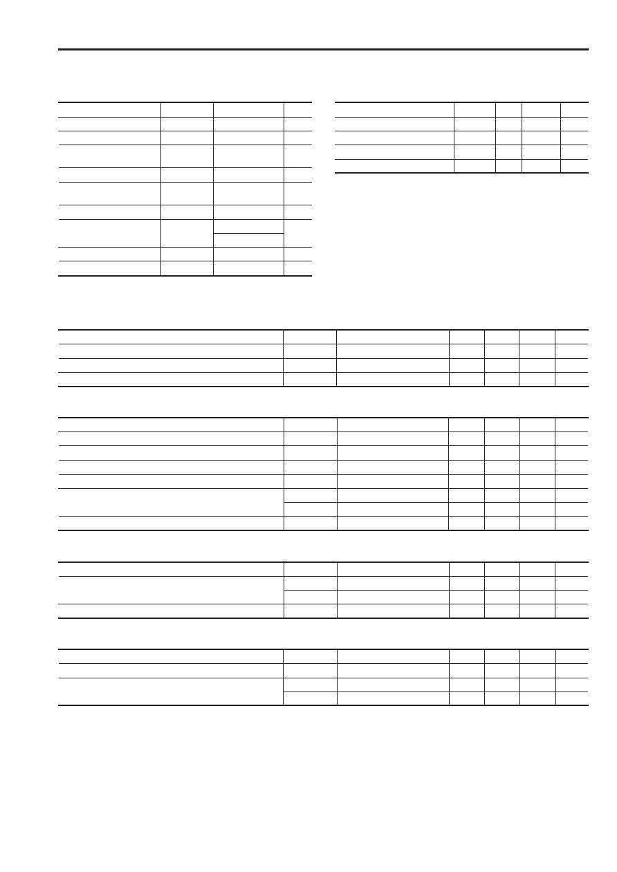
s Absolute maximum ratings
Common to FA5304AP(S) and FA5305AP(S)
Item
Symbol
Rating
Unit
VCC
30
V
IO
±1.5
A
VIN
4V
VFB
4V
VIS
–0.3 to +4
V
ICS
2mA
Pd
800 (DIP-8) *1
mW
550 (SOP-8) *2
Topr
–30 to +85
°C
Tstg
–40 to +150
°C
s Recommended operating conditions
Common to FA5304AP(S) and FA5305AP(S)
Item
Symbol
Min.
Max.
Unit
Supply voltage
VCC
10
30
V
Error amplifier feedback resistor
RNF
100
k
Soft-start capacitor
CS
0.1
1
F
Oscillation frequency
fOSC
5
600
kHz
Supply voltage
Output current
Error amplifier input
voltage
Feedback terminal input voltage
Overcurrent detection
terminal input voltage
CS terminal input current
Total power dissipation
(Ta = 25
°C)
Operating temperature
Storage temperature
Notes:
*1 Derating factor Ta > 25°C : 8.0mW/°C ( on PC board )
*2 Derating factor Ta > 25°C : 5.5mW/°C ( on PC board )
s Electrical characteristics (Ta=25
°C, VCC=18V,fosc=135kHz)
Oscillator section
Common to FA5304AP(S) and FA5305AP(S)
Item
Symbol
Test condition
Min.
Typ.
Max.
Unit
Oscillation frequency
fOSC
CT = 360pF
112
135
148
kHz
Frequency variation 1 (due to supply voltage change)
fdv
VCC = 10 to 30V
±1%
Frequency variation 2 (due to temperature change)
fdT
Ta = –30 to +85
°C
±4%
Error amplifier section
Common to FA5304AP(S) and FA5305AP(S))
Item
Symbol
Test condition
Min.
Typ.
Max.
Unit
Reference voltage
VB
1.90
2.00
2.10
V
Input bias current
IB
V1 = 2V
–500
–50
nA
Open-loop voltage gain
AV
80
dB
Unity-gain bandwidth
fT
1.0
MHz
Maximum output voltage (Pin 2)
VOM+
RNF = 100k
2.70
V
VOM–
RNF = 100k
200
mV
Output source current (Pin 2)
IMO+
VOM = 1V
–100
–50
A
Pulse width modulation circuit section
Common to FA5304AP(S) and FA5305AP(S)
Item
Symbol
Test condition
Min.
Typ.
Max.
Unit
Input threshold voltage (Pin 2)
VTH FBO
Duty cycle = 0%
0.80
1.00
1.20
V
VTH FBM
Duty cycle =
DMAX
1.70
1.90
2.10
V
Maximum duty cycle
DMAX
42
45
50
%
Soft-start circuit section
Common to FA5304AP(S) and FA5305AP(S)
Item
Symbol
Test condition
Min.
Typ.
Max.
Unit
Charge current (Pin 8)
ICHG
Pin 8 = 0V
–15
–10
–5
A
Input threshold voltage (Pin 8)
VTH CSO
Duty cycle = 0%
0.80
1.00
1.20
V
VTH CSM
Duty cycle =
DMAX
1.70
1.90
2.10
V
相关PDF资料 |
PDF描述 |
|---|---|
| FA5304AP | 1.5 A SWITCHING CONTROLLER, 600 kHz SWITCHING FREQ-MAX, PDIP8 |
| FA5314S | 1.5 A SWITCHING CONTROLLER, 600 kHz SWITCHING FREQ-MAX, PDSO8 |
| FA5310BP | 1.5 A SWITCHING CONTROLLER, 600 kHz SWITCHING FREQ-MAX, PDIP8 |
| FA5311BP | 1.5 A SWITCHING CONTROLLER, 600 kHz SWITCHING FREQ-MAX, PDIP8 |
| FA5315P | 1.5 A SWITCHING CONTROLLER, 600 kHz SWITCHING FREQ-MAX, PDIP8 |
相关代理商/技术参数 |
参数描述 |
|---|---|
| FA5305APS | 制造商:FUJI 制造商全称:Fuji Electric 功能描述:Bipolar IC For Switching Power Supply Control |
| FA5305AS | 制造商:未知厂家 制造商全称:未知厂家 功能描述:(367.00 k) |
| FA531 | 制造商:未知厂家 制造商全称:未知厂家 功能描述:FA531硅NPN型超高频大功率晶体管 |
| FA5310 | 制造商:FUJI 制造商全称:Fuji Electric 功能描述:Bipolar IC For Switching Power Supply Control |
| FA5310BP | 制造商:FUJI 制造商全称:Fuji Electric 功能描述:Bipolar IC For Switching Power Supply Control |
发布紧急采购,3分钟左右您将得到回复。