- 您现在的位置:买卖IC网 > PDF目录67412 > FA5500AN (FUJI ELECTRIC CO LTD) 1 A SWITCHING CONTROLLER, PDSO8 PDF资料下载
参数资料
| 型号: | FA5500AN |
| 厂商: | FUJI ELECTRIC CO LTD |
| 元件分类: | 稳压器 |
| 英文描述: | 1 A SWITCHING CONTROLLER, PDSO8 |
| 封装: | SO-8 |
| 文件页数: | 8/26页 |
| 文件大小: | 228K |
| 代理商: | FA5500AN |
FA5500AP/AN, FA5501AP/AN
16
Quality is our message
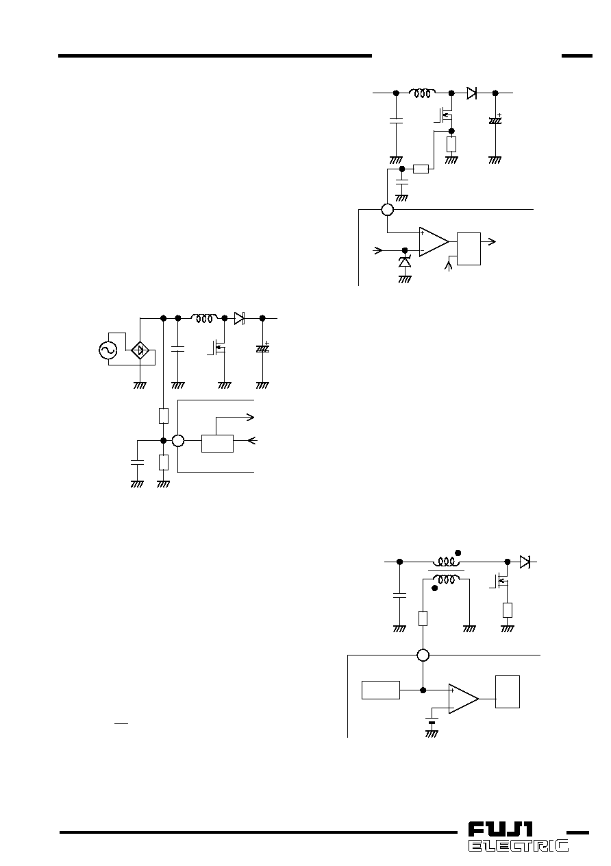
(4)Multiplier
The multiplier is a circuit to control input current into
sinusoidal waveform.
One of the inputs is connected to MUL pin. The
rectified AC line voltage is divided down by resistor and
monitored by MUL pin. The other input is internally
connected to the output of error amplifier. Typically, the
output of error amplifier is almost DC over a given AC
line
cycle.
Therefore,
the
multiplier
outputs
the
sinusoidal voltage of which amplitude changes in
proportion to the output of error amplifier. This output
becomes the threshold of current comparator and the
AC input current is controlled into sinusoidal waveform.
Based on the dynamic range of multiplier, the peak
voltage applied to MUL pin should be within 2.5 V in
normal operation.
The
rectified
AC
line
voltage
contains
much
switching noises from Q1. To avoid the influence of the
noises, a capacitor (C6) is connected for a filter.
3
MUL
CUR.comp
ERRAMP
MUL
R4
R3
L1
C1
Q1
D1
AC
C6
C2
Fig.7
Multiplier circuit
(5)Current sense comparator
One of the inputs is internally connected to the
output of multiplier as the threshold. The other input is
connected to IS pin to monitor the MOSFET source
current converted to voltage by current sense resistor
(Rs). In each switching cycle, when MOSFET current
reaches up to the threshold determined by the
multiplier, the output of current comparator turns high
and reset the RS flip-flop. As a result, MOSFET turns
off, and the on cycle of MOSFET is over.
The threshold voltage of current comparator is
internally clamped to 1.8V (max.). Therefore, when
PFC starts up or load and input voltage changes rapidly,
the maximum current of MOSFET is limited at the value
calculated with the following equation:
Rs
1.8
.)
Id(max
=
To prevent malfunction by noises, RC filter is typically
connected between IS pin and the current sense
resistor Rs.
4
L1
D1
C1
Q1
C2
Rs
R6
C4
IS
MUL
1.8V
(max)
CUR.comp
ZCD.comp
R
S
Q
Output
circuit
Fig.8
Current sense comparator circuit
(6)Zero current detector
This IC operates in critical conduction current mode
without a fixed frequency oscillator. The zero current
detector circuit (ZCD) detects the inductor current
reaches zero to turn the MOSFET on at the next
switching cycle.
The voltage of auxiliary winding (sub) is monitored by
ZCD pin as shown in Fig. 9. During OFF period of
MOSFET, positive voltage occurs in the auxiliary
winding. When the inductor current reaches zero, the
voltage of auxiliary winding falls rapidly. ZCD.comp.
detects it and sets the RS flip-flop to turn the MOSFET
on at the next switching cycle.
The voltage of auxiliary winding varies significantly
according to input and output voltage. To protect the IC
against the various voltages, a clamp circuit is built in
with the upper limit of 7.6V(typ.) and the lower limit of
0.6V(typ.).
R
S
Q
Clamp
5
L1
D1
sub
Q1
Rs
R5
ZCD
ZCD.comp
1.33/1.5V
C1
Clamp circuit
Fig.9
ZCD circuit
A resistor for current limit is typically connected
between the ZCD pin and the auxiliary winding
because of rating current of ZCD pin.
相关PDF资料 |
PDF描述 |
|---|---|
| FA5500AP | 1 A SWITCHING CONTROLLER, PDIP8 |
| FA5516N | 1 A SWITCHING CONTROLLER, 143 kHz SWITCHING FREQ-MAX, PDSO8 |
| FA5517N | 1 A SWITCHING CONTROLLER, 110 kHz SWITCHING FREQ-MAX, PDSO8 |
| FA5516P | 1 A SWITCHING CONTROLLER, 143 kHz SWITCHING FREQ-MAX, PDIP8 |
| FA5517P | 1 A SWITCHING CONTROLLER, 110 kHz SWITCHING FREQ-MAX, PDIP8 |
相关代理商/技术参数 |
参数描述 |
|---|---|
| FA5500AP/AN | 制造商:未知厂家 制造商全称:未知厂家 功能描述: |
| FA550-10PAK | 制造商:Black Box Corporation 功能描述:DB15 Male Transceiver Connector Kit, 10-Pack |
| FA5501AP/AN | 制造商:未知厂家 制造商全称:未知厂家 功能描述: |
| FA5502 | 制造商:未知厂家 制造商全称:未知厂家 功能描述:FA5502P/M is a control IC for a power factor correction system. |
| FA5502M-H1 | 制造商:Fuji Electric 功能描述: |
发布紧急采购,3分钟左右您将得到回复。