- 您现在的位置:买卖IC网 > PDF目录67412 > FA5500AP (FUJI ELECTRIC CO LTD) 1 A SWITCHING CONTROLLER, PDIP8 PDF资料下载
参数资料
| 型号: | FA5500AP |
| 厂商: | FUJI ELECTRIC CO LTD |
| 元件分类: | 稳压器 |
| 英文描述: | 1 A SWITCHING CONTROLLER, PDIP8 |
| 封装: | DIP-8 |
| 文件页数: | 14/26页 |
| 文件大小: | 228K |
| 代理商: | FA5500AP |
FA5500AP/AN, FA5501AP/AN
21
Quality is our message
In actual circuit, the value of R5 also influences
MOSFET switching.
MOSFET(Q1) turns on when the current of inductor
L1 reaches zero. Just before turning on, the drain
voltage of MOSFET (Vds) begins sinusoidal oscillation
because of resonance of L1 and the parasitic capacitor.
If the value of R5 is set properly, MOSFET can be
turned on at the bottom of the voltage oscillation. This
can minimize the switching loss and surge current at
turn on. If the value of R5 is too small, MOSFET turns
on too early and if it is too large MOSFET turns on too
late. The adequate value of R5 depends on each
circuits or input and output conditions. Therefore,
determine the most appropriate value by evaluating the
operation in the actual circuit.
t
Vds
0
Fig.17
Vds waveform at turn on
(with adequate R5)
t
Vds
0
t
Vds
0
R5 is too small.
R5 is too large.
Fig.18
Vds waveform at turn on
(with inadequate R5)
(1-5)
Vcc Pin circuit
The startup resistor R7 should satisfy the following
formula in order to supply with at least 20A of IC
startup current.
6
10
20
.)
(max
Von
.)
Vac(min
2
7
R
×
×
<
Where,
Von(max.): maximum voltage of startup threshold of
UVLO
FA5500A: Von(max.)=13V
FA5501A: Von(max.)=14.5V
This formula is, however, just the minimum condition
to start the IC. The startup time required for PFC
converter must also be decided on. The value of R7
should be tested and determined in actual circuit for
appropriate startup time.
8
L1
D2
R7
C1
VCC
C5
Fig.19
Vcc pin circuit
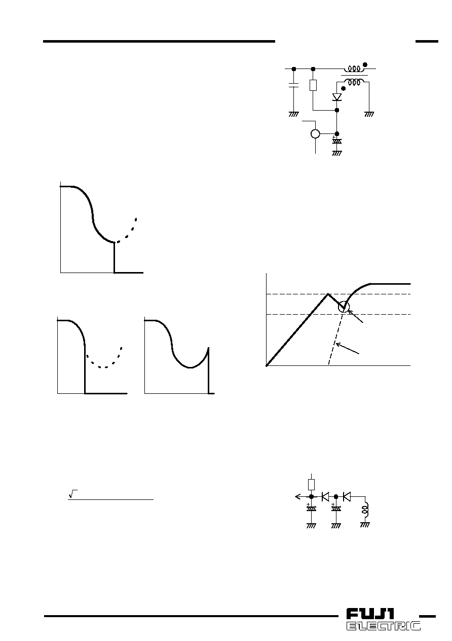
In steady state, Vcc is supplied from the auxiliary
winding of inductor. When the IC is just starting up,
however, it takes time for the voltage from auxiliary
winding to rise enough. The value of capacitor C5
connected to Vcc pin should be determined to prevent
Vcc from falling below the UVLO threshold voltage
during the this period. The capacity of C5 should be
tested and determined in the actual circuit because the
time lag is different in each circuit.
UVLO
ON
UVLO
OFF
Auxiliary winding voltage
Vcc
Time t
Vcc must not drop
below UVLO OFF.
Fig.20
Vcc voltage at startup
Even after PFC starts up, Vcc may fall due to rapidly
changes of the load or inputs. To prevent the IC from
stopping in those cases, the circuit shown in Fig.21 is
effective to prolong the hold time of the Vcc voltage.
After the PFC converter starts up, Vcc is supplied
through C7. Therefore, you can prolong the hold time of
Vcc by using a large capacity for C7.
R7
D2
D3
C5
C7
sub
VCC
Fig.21
Vcc pin circuit (2)
In some case, the Vcc voltage cannot be supplied
enough in light load condition. In this case, the circuit
shown in Fig.22 may be effective to improve the Vcc. In
this circuit, R10 suppress the surge current of MOSFET
at turn on to prevent the malfunctions. (See (1-7) IS pin
相关PDF资料 |
PDF描述 |
|---|---|
| FA5516N | 1 A SWITCHING CONTROLLER, 143 kHz SWITCHING FREQ-MAX, PDSO8 |
| FA5517N | 1 A SWITCHING CONTROLLER, 110 kHz SWITCHING FREQ-MAX, PDSO8 |
| FA5516P | 1 A SWITCHING CONTROLLER, 143 kHz SWITCHING FREQ-MAX, PDIP8 |
| FA5517P | 1 A SWITCHING CONTROLLER, 110 kHz SWITCHING FREQ-MAX, PDIP8 |
| FA5518P | 1 A SWITCHING CONTROLLER, 66 kHz SWITCHING FREQ-MAX, PDIP8 |
相关代理商/技术参数 |
参数描述 |
|---|---|
| FA5500AP/AN | 制造商:未知厂家 制造商全称:未知厂家 功能描述: |
| FA550-10PAK | 制造商:Black Box Corporation 功能描述:DB15 Male Transceiver Connector Kit, 10-Pack |
| FA5501AP/AN | 制造商:未知厂家 制造商全称:未知厂家 功能描述: |
| FA5502 | 制造商:未知厂家 制造商全称:未知厂家 功能描述:FA5502P/M is a control IC for a power factor correction system. |
| FA5502M-H1 | 制造商:Fuji Electric 功能描述: |
发布紧急采购,3分钟左右您将得到回复。