- 您现在的位置:买卖IC网 > PDF目录22229 > FAN4800AMY (Fairchild Semiconductor)IC PFC CONTROLLER CCM/DCM 16SOIC PDF资料下载
参数资料
| 型号: | FAN4800AMY |
| 厂商: | Fairchild Semiconductor |
| 文件页数: | 20/24页 |
| 文件大小: | 931K |
| 描述: | IC PFC CONTROLLER CCM/DCM 16SOIC |
| 标准包装: | 1 |
| 模式: | 连续导电(CCM),间歇导电(DCM) |
| 频率 - 开关: | 66kHz ~ 84kHz |
| 电流 - 启动: | 100µA |
| 电源电压: | 11 V ~ 16.5 V |
| 工作温度: | -40°C ~ 125°C |
| 安装类型: | 表面贴装 |
| 封装/外壳: | 16-SOIC(0.154",3.90mm 宽) |
| 供应商设备封装: | 16-SOIC |
| 包装: | 标准包装 |
| 其它名称: | FAN4800AMYDKR |
?2008 Fairchild Semiconductor Corporation
www.fairchildsemi.com
FAN4800A/C, FAN4801/02/02L " Rev. 1.0.3
20
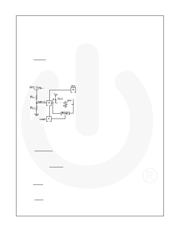
Two-Level PFC Function
To improve the efficiency, the system can reduce PFC
switching loss at low line and light load by reducing the
PFC output voltage. The two-level PFC output of
FAN4801/02/02L can be programmable.
As Figure 47 shows, FAN4801/02/02L detect VEA pin
and VRMS pin to determine the system operates low
line and light load or not. At the second-level PFC, there
is a current of 20礎 through R
F2
from FBPFC pin. So
the second-level PFC output voltage can be calculated
as.
+
@
?/DIV>
-
?/DIV>
1
2
2
2
(2.5
20
)
F F
F
F
R R
Output
V
uA R
R
(3)
For example, if the second-level PFC output voltage is
expected as 300V and normal voltage is 387V,
according to the equation, R
F2
is 28k& R
F1
is 4.3M&.
The programmable range of second level PFC output
voltage is 340V ~ 300V.
Figure 47. Two-Level PFC Scheme
Oscillator (R
T
/C
T
)
The oscillator frequency is determined by the values of
R
T
and C
T
, which determine the ramp and off-time of
the oscillator output clock:
/
/
1
RT CT
RT CT DEAD
f
t
t
=
+
(4)
The dead time of the oscillator is derived from the
following equation:
/
1
ln
3.8
RT CT
T
T
VREF
t
C R
VREF
-
?/DIV>
?/DIV>
=
?/DIV>
?/DIV>
?/DIV>
?/DIV>
-
?/DIV>
?/DIV>
(5)
at V
REF
=7.5V and t
RT/CT
=CT x RT x 0.56.
The dead time of the oscillator is determined using:
2.8
360
7.78
DEAD
T
T
V
t
C
C
mA
=
?/DIV>
=
?/DIV>
(6)
The dead time is so small (t
RT/CT
>>t
DEAD
) that the
operating frequency can typically be approximated by:
/
/
1
RT CT
RT CT
f
t
=
(7)
Pulse Width Modulator (PWM)
The operation of the PWM section is straightforward,
but there are several points that should be noted.
Foremost among these is the inherent synchronization
of PWM with the PFC section of the device, from which
it also derives its basic timing. The PWM is capable of
current-mode or voltage-mode operation. In current-
mode applications, the PWM ramp (RAMP) is usually
derived directly from a current sensing resistor or
current transformer in the primary of the output stage. It
is thereby representative of the current flowing in the
converters output stage. I
LIMIT
, which provides cycle-by-
cycle current limiting, is typically connected to RAMP in
such applications. For voltage-mode operation and
certain specialized applications, RAMP can be
connected to a separate RC timing network to generate
a voltage ramp against which FBPWM is compared.
Under these conditions, the use of voltage feed-forward
from the PFC bus can assist in line regulation accuracy
and response. As in current-mode operation, the I
LIMIT
input is used for output stage over-current protection.
No voltage error amplifier is included in the PWM stage,
as this function is generally performed on the output
side of the PWMs isolation boundary. To facilitate the
design of opto-coupler feedback circuitry, an offset has
been built into the PWMs RAMP input that allows
FBPWM to command a 0% duty cycle for input voltages
below typical 1.5V.
PWM Cycle-By-Cycle Current Limiter
The ILIMIT pin is a direct input to the cycle-by-cycle
current limiter for the PWM section. Should the input
voltage at this pin ever exceed 1V, the output flip-flop is
reset by the clock pulse at the start of the next PWM
power cycle. When the I
LIMIT
triggers the cycle-by-cycle
bi-cycle current, it limits the PWM duty cycle mode and
the power dissipation is reduced during the dead-short
condition.
V
IN
OK Comparator
The V
IN
OK comparator monitors the DC output of the
PFC and inhibits the PWM if the voltage on FBPFC is
less than its nominal 2.4V. Once the voltage reaches
2.4V, which corresponds to the PFC output capacitor
being charged to its rated boost voltage, the soft-start
begins.
PWM Soft-Start (SS)
PWM startup is controlled by selection of the external
capacitor at soft-start. A current source of 10礎
supplies the charging current for the capacitor and
startup of the PWM begins at 1.5V.
相关PDF资料 |
PDF描述 |
|---|---|
| FAN4800CMY | IC PFC CONTROLLER CCM/DCM 16SOIC |
| RAC04-05SA/277 | CONV AC/DC 4W 5V OUT SINGLE T/H |
| 345-144-540-801 | CARDEDGE 144POS DUAL .100 GREEN |
| RAC06-12DC | CONV AC/DC 6W +/-12VOUT MULTI |
| GBM11DRYI-S13 | CONN EDGECARD 22POS .156 EXTEND |
相关代理商/技术参数 |
参数描述 |
|---|---|
| FAN4800ANY | 功能描述:电流型 PWM 控制器 PWM PFC Combo RoHS:否 制造商:Texas Instruments 开关频率:27 KHz 上升时间: 下降时间: 工作电源电压:6 V to 15 V 工作电源电流:1.5 mA 输出端数量:1 最大工作温度:+ 105 C 安装风格:SMD/SMT 封装 / 箱体:TSSOP-14 |
| FAN4800AS | 制造商:FAIRCHILD 制造商全称:Fairchild Semiconductor 功能描述:PFC/PWM Controller Combination |
| FAN4800ASMY | 功能描述:功率因数校正 IC PFC + PWM Controller Combo RoHS:否 制造商:Fairchild Semiconductor 开关频率:300 KHz 最大功率耗散: 最大工作温度:+ 125 C 安装风格:SMD/SMT 封装 / 箱体:SOIC-8 封装:Reel |
| FAN4800ASMY_F116 | 功能描述:功率因数校正 IC PFC + PWM Ctrl Combo RoHS:否 制造商:Fairchild Semiconductor 开关频率:300 KHz 最大功率耗散: 最大工作温度:+ 125 C 安装风格:SMD/SMT 封装 / 箱体:SOIC-8 封装:Reel |
| FAN4800ASNY | 功能描述:功率因数校正 IC PFC + PWM Controller Combo RoHS:否 制造商:Fairchild Semiconductor 开关频率:300 KHz 最大功率耗散: 最大工作温度:+ 125 C 安装风格:SMD/SMT 封装 / 箱体:SOIC-8 封装:Reel |
发布紧急采购,3分钟左右您将得到回复。