- 您现在的位置:买卖IC网 > PDF目录68994 > FC400R1-29 1-OUTPUT 400 W DC-DC REG PWR SUPPLY MODULE PDF资料下载
参数资料
| 型号: | FC400R1-29 |
| 元件分类: | 电源模块 |
| 英文描述: | 1-OUTPUT 400 W DC-DC REG PWR SUPPLY MODULE |
| 文件页数: | 17/18页 |
| 文件大小: | 521K |
| 代理商: | FC400R1-29 |
8
Tyco Electronics Corp.
Advance Data Sheet
July 2001
18 Vdc to 36 Vdc Input, 28 Vdc Output; 400 W
FC400R1-29 Power Module; dc-dc Converter:
Safety Considerations
For safety-agency approval of the system in which the
power module is used, the power module must be
installed in compliance with the spacing and separation
requirements of the end-use safety agency standard,
i.e.,
UL60950, CSA C22.2 No. 60950-00, and VDE
0805 (IEC60950).
If the input source is non-SELV (ELV or a hazardous
voltage greater than 60 Vdc and less than or equal to
75 Vdc), for the module’s output to be considered
meeting the requirements of safety extra-low voltage
(SELV), all of the following must be true:
s
The input source is to be provided with reinforced
insulation from any hazardous voltages, including the
ac mains.
s
One VI pin and one VO pin are to be grounded, or
both the input and output pins are to be kept floating.
s
The input pins of the module are not operator acces-
sible.
s
Another SELV reliability test is conducted on the
whole system, as required by the safety agencies, on
the combination of supply source and the subject
module to verify that under a single fault, hazardous
voltages do not appear at the module’s output.
Note: Do not ground either of the input pins of the
module without grounding one of the output pins.
This may allow a non-SELV voltage to appear
between the output pin and ground.
The power module has extra-low voltage (ELV) outputs
when all inputs are ELV.
The input to these units is to be provided with a maxi-
mum 30 A fast-acting fuse in the ungrounded lead.
Feature Descriptions
Overcurrent Protection
To provide protection in a fault (output overload) condi-
tion, the unit is equipped with internal current-limiting
circuitry and can endure current limiting for an unlim-
ited duration. At the point of current-limit inception, the
unit shifts from voltage control to current control. If the
output voltage is pulled very low during a severe fault,
the current-limit circuit can exhibit either foldback or
tailout characteristics (output-current decrease or
increase). The unit operates normally once the output
current is brought back into its specified range.
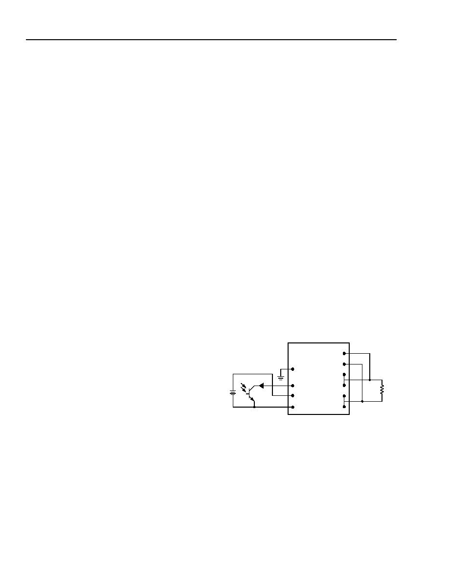
Remote On/Off
To turn the power module on and off, the user must
supply a switch to control the voltage between the on/off
terminal and the VI(–) terminal (Von/off). The switch can be
an open collector or equivalent (see Figure 11). A logic
low is Von/off = 0 V to 1.2 V, during which the module is on.
The maximum Ion/off during a logic low is 1 mA. The switch
should maintain a logic-low voltage while sinking 1 mA.
During a logic high, the maximum Von/off generated by
the power module is 15 V. The maximum allowable
leakage current of the switch at Von/off = 15 V is 50 A.
If not using the remote on/off feature, short the
ON/OFF pin to VI(–).
8-580 (F).d
Figure 11. Remote On/Off Implementation
+
Ion/off
–
Von/off
CASE
ON/OFF
VI(+)
VI(–)
SENSE(+)
SENSE(–)
VO(+)
VO(–)
相关PDF资料 |
PDF描述 |
|---|---|
| FE150F | 1-OUTPUT 150 W DC-DC REG PWR SUPPLY MODULE |
| FE150F9 | 1-OUTPUT 150 W DC-DC REG PWR SUPPLY MODULE |
| FE200A9 | 1-OUTPUT 200 W DC-DC REG PWR SUPPLY MODULE |
| FE200A98 | 1-OUTPUT 200 W DC-DC REG PWR SUPPLY MODULE |
| FGDS-20A-50V/T | 1-OUTPUT 300 W DC-DC UNREG PWR SUPPLY MODULE |
相关代理商/技术参数 |
参数描述 |
|---|---|
| FC40150-0 | 制造商:Amphenol Corporation 功能描述:LEAD 2.54MM F/F 150MM 40WA 制造商:Amphenol Aerospace 功能描述:LEAD, 2.54MM, F/F, 150MM, 40WAY 制造商:Amphenol Corporation 功能描述:LEAD, 2.54MM, F/F, 150MM, 40WAY; Connector Type A:IDC Female; Connector Type B:IDC Socket; No. of Conductors:40; Pitch Spacing:2.54mm; Cable Length - Imperial:5.91"; Cable Length - Metric:150mm; Jacket Colour:Grey; SVHC:No SVHC ;RoHS Compliant: Yes |
| FC40150-S | 制造商:Amphenol Corporation 功能描述:LEAD 2.54MM F/F S/R 150MM 制造商:Amphenol Aerospace 功能描述:LEAD, 2.54MM, F/F, S/R, 150MM, 40WAY 制造商:Amphenol Corporation 功能描述:LEAD, 2.54MM, F/F, S/R, 150MM, 40WAY; Connector Type A:IDC Female; Connector Type B:IDC Socket; No. of Conductors:40; Pitch Spacing:2.54mm; Cable Length - Imperial:5.91"; Cable Length - Metric:150mm; Jacket Colour:Grey; SVHC:No SVHC ;RoHS Compliant: Yes |
| FC4016D | 制造商:POSITR 功能描述: 制造商:Positronic Industries 功能描述: |
| FC-402-2 | 制造商:Struthers-Dunn 功能描述: |
| FC-402-3 | 制造商:Struthers-Dunn 功能描述: |
发布紧急采购,3分钟左右您将得到回复。