- 您现在的位置:买卖IC网 > PDF目录79144 > FK1601-9RDDT 1-OUTPUT DC-DC REG PWR SUPPLY MODULE PDF资料下载
参数资料
| 型号: | FK1601-9RDDT |
| 元件分类: | 电源模块 |
| 英文描述: | 1-OUTPUT DC-DC REG PWR SUPPLY MODULE |
| 封装: | HEAT SINK, METAL, CASE K02, MODULE |
| 文件页数: | 6/27页 |
| 文件大小: | 640K |
| 代理商: | FK1601-9RDDT |
第1页第2页第3页第4页第5页当前第6页第7页第8页第9页第10页第11页第12页第13页第14页第15页第16页第17页第18页第19页第20页第21页第22页第23页第24页第25页第26页第27页
Rugged Environment
DC-DC Converters >100 W
K-Family
Edition 2/96 - Melcher AG
8 - 15
MELCHER
The Power Partners.
8.1
Test Sockets (Main output only 1)
Test sockets for measuring the output voltage
Uo1 are lo-
cated at the front of the module. The positive test socket is
protected by a series resistor (see Functional Description,
block diagrams). The voltage measured at the test sockets
is approximately 30 mV lower than the value measured at
the output terminals.
1 In case of double output units externally connected in series for
Uo = 24 V, 30 V or 48 V the monitored output voltage is 12 V,
15 V or 24 V respectively.
Output Protection
Each output is protected against overvoltage which could
occur due to a failure of the control circuit by means of a
voltage suppressor diode which, under worst case condi-
tions, may become a short circuit. The suppressor diode
are not designed to withstand externally applied over-
voltages. Overload at any of the two outputs will cause a
shut-down of both outputs. A red LED indicates the over-
load condition.
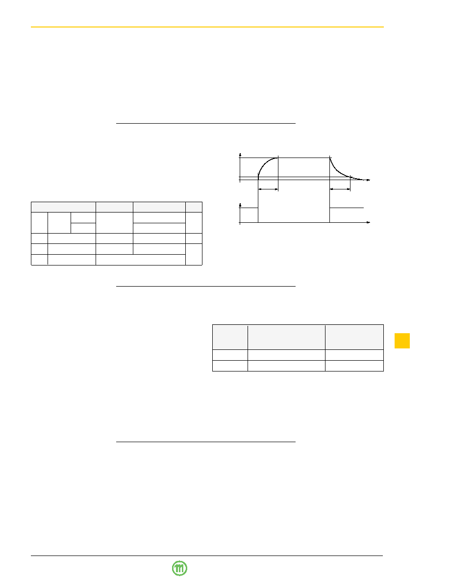
Inhibit Function
The outputs of a module may be enabled or disabled by
means of a logic signal (TTL, CMOS etc.) applied to the in-
hibit input. If the inhibit function is not required, connect the
inhibit pin 18 to pin 14 to enable the outputs (active low
logic, fail safe).
Fig. 10
Typical output response as a function of inhibit control
Table 9: Inhibit characteristics
Characteristic
Conditions
min
typ
max Unit
Uinh Inhibit
Uo = on Ui min…Ui max
–50
0.8
V
voltage
Uo = off
2.4
50
Iinh
Inhibit current
Uinh = 0
–400
A
tr
Rise time
30
ms
tf
Fall time
depending on
Io
0
t
0
Inhibit
1
0.1
Uo nom
Output
tr
tf
Note:
– Parallel connection of double output units should always
include both, main and second output to maintain good
regulation of both outputs.
– Series connection of second outputs without involving
their main outputs should be avoided as regulation may
be poor.
– The maximum output current is limited by the output with
the lowest current limitation if several outputs are con-
nected in series.
– Not more than 5 units should be connected in parallel.
Parallel or Series Connection of Units
Single or double output units with equal nominal output volt-
age can be connected in parallel without any precautions
using option T.
With option T (current sharing), all units share the current
approximately equally.
Single output units and/or main and second outputs of dou-
ble output units can be connected in series with any other
(similar) output.
Sense Lines
(Only for single output units 5.1 V, 12 V, 15 V, 24 V)
This feature enables compensation for voltage drops
across the connector contacts and if necessary, across the
load lines. If the sense lines are connected at the load
rather than directly at the connector, the user should ensure
that
Uo max (between Vo1+ and Vo1–) is not exceeded. We
recommend connecting the sense lines directly at the fe-
male connector.
For further information, please refer to "Application Notes ".
To ensure correct operation, both sense lines should be
connected to their respective power outputs and the volt-
age difference between any sense line and its respective
power output pin (as measured on the connector) should
not exceed the following values:
Table 10: Voltage compensation allowed using sense
lines
Output
Total voltage difference
Voltage difference
voltage
between sense lines and
between
their respective outputs
Vo– and S–
5.1 V
< 0.5 V
< 0.25 V
12 V, 15 V
< 1.0 V
< 0.25 V
If the output voltages are increased above
Uo nom via R-in-
put control, option P setting, remote sensing or option T, the
output currents must be reduced accordingly so that
Po nom is not exceeded.
相关PDF资料 |
PDF描述 |
|---|---|
| FM1001-7RD7H | 1-OUTPUT 50 W DC-DC REG PWR SUPPLY MODULE |
| FM1001-7RV0H | 1-OUTPUT 50 W DC-DC REG PWR SUPPLY MODULE |
| FM1001-9PD6F | 1-OUTPUT 50 W DC-DC REG PWR SUPPLY MODULE |
| FM1001-9PV3AF | 1-OUTPUT 50 W DC-DC REG PWR SUPPLY MODULE |
| FM1001-9RD0H | 1-OUTPUT 50 W DC-DC REG PWR SUPPLY MODULE |
相关代理商/技术参数 |
参数描述 |
|---|---|
| FK161EIHM0.032768 | 功能描述:CRYSTAL 32.768KHZ 12.5PF SMD 制造商:fox electronics 系列:FK161 包装:剪切带(CT) 零件状态:在售 类型:kHz 晶体(音叉) 频率:32.768kHz 频率稳定度:- 频率容差:±20ppm 负载电容:12.5pF 工作模式:基谐 工作温度:-40°C ~ 85°C 等级:- 安装类型:表面贴装 封装/外壳:2-SMD,无引线 大小/尺寸:0.063" 长 x 0.039" 宽(1.60mm x 1.00mm) 高度 - 安装(最大值):0.020"(0.50mm) 标准包装:1 |
| FK1630003 | 功能描述:OSC 16.384MHZ 3.3V SMD RoHS:是 类别:晶体和振荡器 >> 振荡器 系列:SaRonix-eCera™ FK 标准包装:1 系列:VG-4512CA 类型:VCXO 频率:153.6MHz 功能:三态(输出启用) 输出:LVPECL 电源电压:3.3V 频率稳定性:- 工作温度:-40°C ~ 85°C 电流 - 电源(最大):60mA 额定值:- 安装类型:表面贴装 尺寸/尺寸:0.276" L x 0.197" W(7.00mm x 5.00mm) 高度:0.071"(1.80mm) 封装/外壳:6-SMD,无引线(DFN,LCC) 包装:Digi-Reel® 电流 - 电源(禁用)(最大):- 其它名称:SER3790DKR |
| FK1630004 | 功能描述:OSC 16.384MHZ 3.3V SMD RoHS:是 类别:晶体和振荡器 >> 振荡器 系列:SaRonix-eCera™ FK 标准包装:1 系列:VG-4512CA 类型:VCXO 频率:153.6MHz 功能:三态(输出启用) 输出:LVPECL 电源电压:3.3V 频率稳定性:- 工作温度:-40°C ~ 85°C 电流 - 电源(最大):60mA 额定值:- 安装类型:表面贴装 尺寸/尺寸:0.276" L x 0.197" W(7.00mm x 5.00mm) 高度:0.071"(1.80mm) 封装/外壳:6-SMD,无引线(DFN,LCC) 包装:Digi-Reel® 电流 - 电源(禁用)(最大):- 其它名称:SER3790DKR |
| FK1630005 | 功能描述:OSC 16.384MHZ 3.3V SMD RoHS:是 类别:晶体和振荡器 >> 振荡器 系列:SaRonix-eCera™ FK 标准包装:1 系列:VG-4512CA 类型:VCXO 频率:153.6MHz 功能:三态(输出启用) 输出:LVPECL 电源电压:3.3V 频率稳定性:- 工作温度:-40°C ~ 85°C 电流 - 电源(最大):60mA 额定值:- 安装类型:表面贴装 尺寸/尺寸:0.276" L x 0.197" W(7.00mm x 5.00mm) 高度:0.071"(1.80mm) 封装/外壳:6-SMD,无引线(DFN,LCC) 包装:Digi-Reel® 电流 - 电源(禁用)(最大):- 其它名称:SER3790DKR |
| FK16C0G1H103J | 功能描述:多层陶瓷电容器MLCC - 含引线 0.01uF 50volts C0G +/-5% RoHS:否 制造商:AVX 电容:470 pF 容差:10 % 电压额定值:3 kV 端接类型:Radial 工作温度范围: 温度系数/代码:X7R 引线间隔:5.08 mm 产品:Automotive MLCCs 引线类型: |
发布紧急采购,3分钟左右您将得到回复。