- 您现在的位置:买卖IC网 > PDF目录7301 > FODM3083 (Fairchild Optoelectronics Group)IC TRIAC ZERO X 800V 5MA 4-MFP PDF资料下载
参数资料
| 型号: | FODM3083 |
| 厂商: | Fairchild Optoelectronics Group |
| 文件页数: | 7/13页 |
| 文件大小: | 0K |
| 描述: | IC TRIAC ZERO X 800V 5MA 4-MFP |
| 产品目录绘图: | 4-MFP Package |
| 标准包装: | 3,000 |
| 电压 - 隔离: | 3750Vrms |
| 通道数: | 1 |
| 电压 - 断路: | 800V |
| 输出类型: | 交流过零三端双向可控硅开关 |
| 电流 - 栅极触发电流 (Igt)(最大): | 5mA |
| 电流 - 保持 (Ih): | 300µA |
| 电流 - DC 正向(If): | 60mA |
| 电流 - 输出 / 通道: | 70mA |
| 安装类型: | 表面贴装 |
| 封装/外壳: | 4-SMD,鸥翼型 |
| 供应商设备封装: | 4-MFP |
| 包装: | 管件 |
�� �
�
�Determining� the� Power� Rating� of� the� Series� Resistors� Used� in� a� Zero-Cross�
�Opto-TRIAC� Driver� Application�
�The� following� will� present� the� calculations� for�
�determining� the� power� dissipation� of� the� current�
�limiting� resistors� found� in� an� opto-TRIAC� driver�
�interface.�
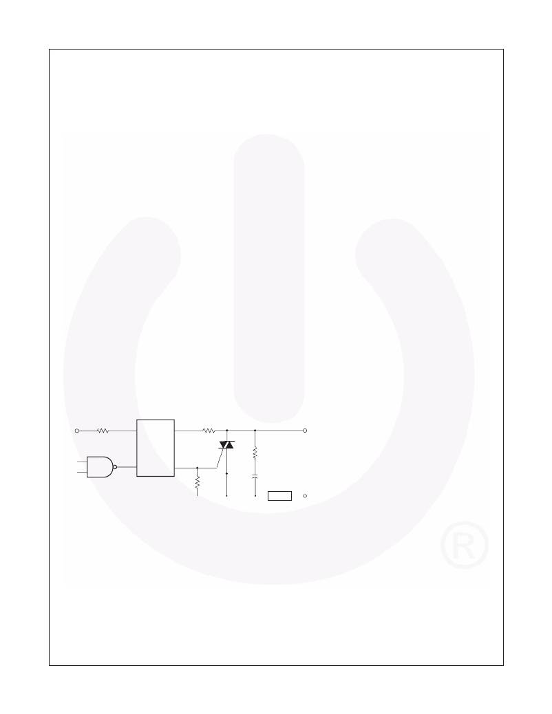
�Figure� 10� shows� a� typical� circuit� to� drive� a� sensitive�
�gate� four� quadrant� power� TRIAC.� This� ?gure� provides�
�typical� resistor� values� for� a� zero� line� cross� detecting�
�opto-TRIAC� when� operated� from� a� mains� voltage� of�
�20V� to� 240V.� The� wattage� rating� for� each� resistor� is�
�not� given� because� their� dissipation� is� dependent� upon�
�characteristics� of� the� power� TRIAC� being� driven.�
�Recall� that� the� opto-TRIAC� is� used� to� trigger� a� four�
�quadrant� power� TRIAC.� Please� note� that� these� opto-�
�TRIACs� are� not� recommended� for� driving�
�“snubberless”� three� quadrant� power� TRIACs.�
�Under� normal� operation,� the� opto-TRIAC� will� ?re� when�
�the� mains� voltage� is� lower� than� the� minimum� inhibit�
�trigger� voltage,� and� the� LED� is� driven� at� a� current�
�greater� than� the� maximum� LED� trigger� current.� As� an�
�example� for� the� FODM3063,� the� LED� trigger� current�
�should� be� greater� than� 5mA,� and� the� mains� voltage� is�
�less� than� 10V� peak.� The� inhibit� voltage� has� a� typical�
�range� of� 10V� minimum� and� 20V� maximum.� This�
�means� that� if� a� suf?cient� LED� current� is� ?owing� when�
�the� mains� voltage� is� less� than� 10V,� the� device� will� ?re.�
�If� a� trigger� appears� between� 10V� and� 20V,� the� device�
�may� ?re.� If� the� trigger� occurs� after� the� mains� voltage�
�has� reached� 20Vpeak,� the� device� will� not� ?re.�
�The� power� dissipated� from� resistors� placed� in� series�
�with� the� opto-TRIAC� and� the� gate� of� the� power� TRIAC�
�is� much� smaller� than� one� would� expect.� These� current�
�handling� components� only� conduct� current� when� the�
�mains� voltage� is� less� than� the� maximum� inhibit�
�voltage.� If� the� opto-TRIAC� is� triggered� when� the� mains�
�voltage� is� greater� than� the� inhibit� voltage,� only� the�
�TRIAC� leakage� current� will� ?ow.� The� power� dissipation�
�in� a� 360� ?� resistor� shown� in� Figure� 10� is� the� product� of�
�the� resistance� (360� ?� )� times� the� square� of� the� current�
�sum� of� main� TRIAC’s� gate� current� plus� the� current�
�?owing� gate� to� the� MT2� resistor� connection� (330� ?� ).�
�This� power� calculation� is� further� modi?ed� by� the� duty�
�factor� of� the� duration� for� this� current� ?ow.� The� duty�
�factor� is� the� ratio� of� the� turn-on� time� of� the� main� TRIAC�
�to� the� sine� of� the� single� cycle� time.� Assuming� a� main�
�TRIAC� turn-on� time� of� 50μs� and� a� 60Hz� mains�
�voltage,� the� duty� cycle� is� approximately� 0.6%.�
�The� opto-TRIAC� only� conducts� current� while� triggering�
�the� main� TRIAC.� Once� the� main� TRIAC� ?res,� its� on-�
�state� voltage� is� typically� lower� than� the� on-state�
�sustaining� voltage� of� the� opto-TRIAC.� Thus,� once� the�
�main� TRIAC� ?res,� the� opto-TRIAC� is� often� shunted� off.�
�This� situation� results� in� very� low� power� dissipation� for�
�both� the� 360� ?� and� 330� ?� resistors,� when� driving� a�
�traditional� four� quadrant� power� TRIAC.�
�If� a� three� quadrant� “snubberless”� TRIAC� is� driven� by�
�the� opto-TRIAC,� the� calculations� are� different.� When�
�the� main� power� TRIAC� is� driving� a� high� power� factor�
�(resistive)� load,� it� shuts� off� during� the� fourth� quadrant.�
�V� CC�
�R� in�
�1�
�2�
�FODM3062�
�FODM3063�
�FODM3082�
�FODM3083�
�4�
�3�
�360� ?�
�39*�
�HOT�
�240� VAC�
�Typical� circuit� for� use� when� hot� line� switching� of� 240VAC�
�is� required.� In� this� circuit� the� “hot”� side� of� the� line� is�
�switched� and� the� load� connected� to� the� cold� or� neutral�
�side.� The� load� may� be� connected� to� either� the� neutral� or�
�hot� line.�
�R� in� is� calculated� so� that� I� F� is� equal� to� the� rated� I� FT� of� the�
�part,� 5mA� for� the� FODM3063/83� and� 10mA� for� the�
�FODM3062/82.� The� 39� ?� resistor� and� 0.01� μ� F� capacitor� are�
�330�
�0.01�
�LOAD�
�NEUTRAL�
�for� snubbing� of� the� triac� and� may� or� may� not� be� necessary�
�depending� upon� the� particular� triac� and� load� used.�
�*�
�For� highly� inductive� loads� (power� factor� <� 0.5),� change� this� value� to� 360� ohms.�
�Figure� 10.� Hot-Line� Switching� Application� Circuit�
�?2006� Fairchild� Semiconductor� Corporation�
�FODM3062,� FODM3063,� FODM3082,� FODM3083� Rev.� 1.0.9�
�7�
�www.fairchildsemi.com�
�相关PDF资料 |
PDF描述 |
|---|---|
| OSTYK50308030 | CONN BARRIER STRIP 8CIRC 9.50MM |
| TB200-04QC4 | TERM BLK 30A 300V 4CIRC DBL ROW |
| TB200-06B | TERM BLK 20A 6CIRC UL CSA IEC CE |
| TB100-06L1L2 | TERM BLK 20A 6CIRC UL CSA |
| HE3621A1240 | RELAY REED SPST 500MA 12V |
相关代理商/技术参数 |
参数描述 |
|---|---|
| FODM3083_NF098 | 功能描述:三极与 SCR 输出光电耦合器 800V Zero Crossing RoHS:否 制造商:Vishay Semiconductors 输出设备:PhotoTriac 每芯片的通道数量: 绝缘电压:3750 Vrms 正向电流:10 mA 正向电压:1.2 V 最大触发电流:10 mA 关断状态下输出电压-VDRM:600 V 最大连续输出电流: 零交叉电路: 封装:Reel |
| FODM3083R1 | 功能描述:三极与 SCR 输出光电耦合器 800V ZERO CROS TRIAC RoHS:否 制造商:Vishay Semiconductors 输出设备:PhotoTriac 每芯片的通道数量: 绝缘电压:3750 Vrms 正向电流:10 mA 正向电压:1.2 V 最大触发电流:10 mA 关断状态下输出电压-VDRM:600 V 最大连续输出电流: 零交叉电路: 封装:Reel |
| FODM3083R2 | 功能描述:三极与 SCR 输出光电耦合器 800V ZERO CROS TRIAC RoHS:否 制造商:Vishay Semiconductors 输出设备:PhotoTriac 每芯片的通道数量: 绝缘电压:3750 Vrms 正向电流:10 mA 正向电压:1.2 V 最大触发电流:10 mA 关断状态下输出电压-VDRM:600 V 最大连续输出电流: 零交叉电路: 封装:Reel |
| FODM3083R2_NF098 | 功能描述:三极与 SCR 输出光电耦合器 800V ZEROCROS TRIAC RoHS:否 制造商:Vishay Semiconductors 输出设备:PhotoTriac 每芯片的通道数量: 绝缘电压:3750 Vrms 正向电流:10 mA 正向电压:1.2 V 最大触发电流:10 mA 关断状态下输出电压-VDRM:600 V 最大连续输出电流: 零交叉电路: 封装:Reel |
| FODM30XX | 制造商:FAIRCHILD 制造商全称:Fairchild Semiconductor 功能描述:4-Pin Full Pitch Mini-Flat Package Random-Phase Triac Driver Output Optocouplers |
发布紧急采购,3分钟左右您将得到回复。