- 您现在的位置:买卖IC网 > PDF目录67560 > FS2540-9EPD2B2 2-OUTPUT 100 W DC-DC REG PWR SUPPLY MODULE PDF资料下载
参数资料
| 型号: | FS2540-9EPD2B2 |
| 元件分类: | 电源模块 |
| 英文描述: | 2-OUTPUT 100 W DC-DC REG PWR SUPPLY MODULE |
| 封装: | METAL, CASE S02, MODULE |
| 文件页数: | 19/31页 |
| 文件大小: | 633K |
| 代理商: | FS2540-9EPD2B2 |
第1页第2页第3页第4页第5页第6页第7页第8页第9页第10页第11页第12页第13页第14页第15页第16页第17页第18页当前第19页第20页第21页第22页第23页第24页第25页第26页第27页第28页第29页第30页第31页
Cassette Style
100 Watt DC-DC Converters
S Series
Edition 1/01.2000
26/31
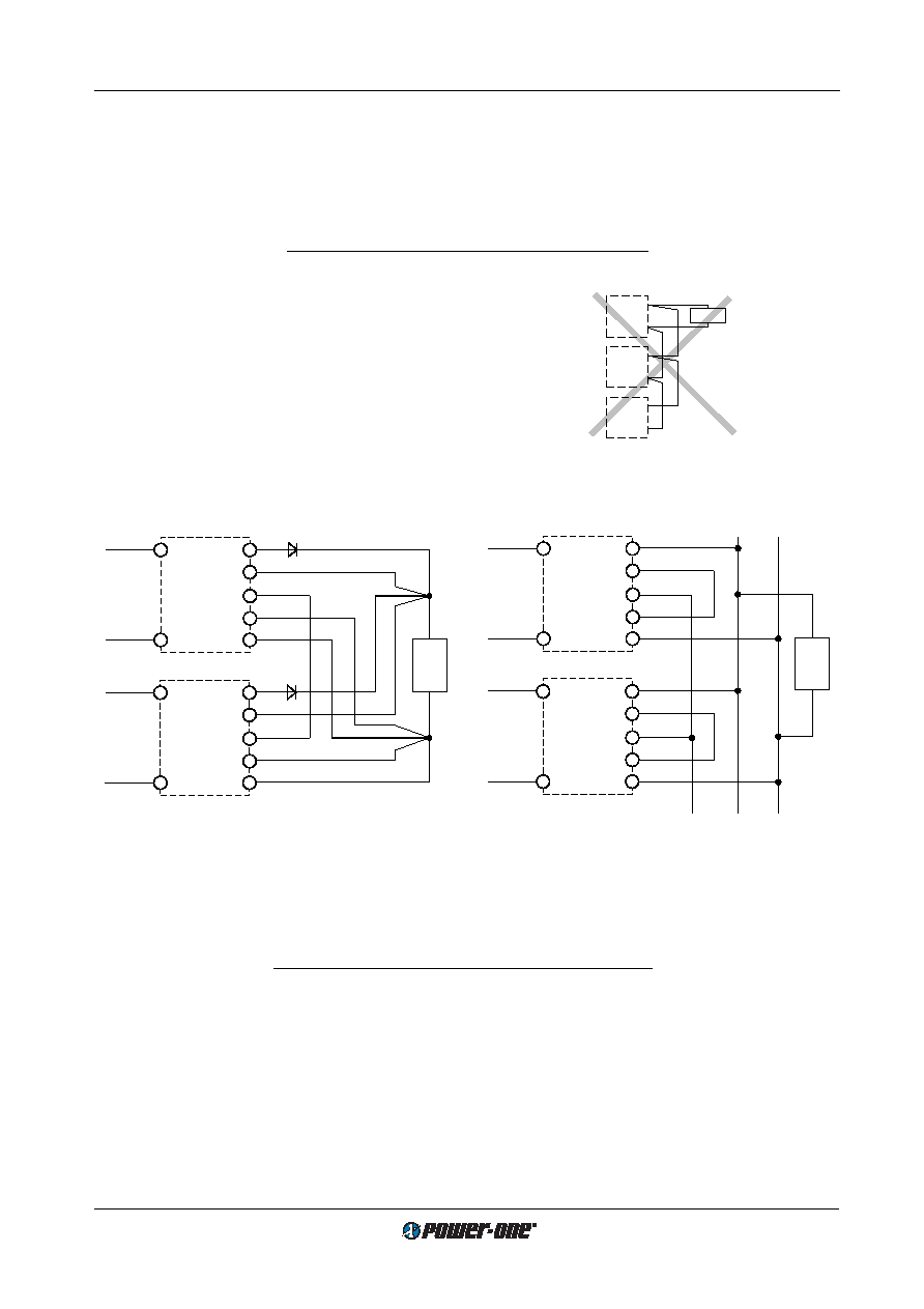
Fig. 28
Paralleling of single output units using option T with the
sense lines connected at the load
1 Leads should have equal length and cross sections and should
run in the same cable loom.
2 Diodes recommended in redundant operation only
3 DC common point
Load
1
2
3
S+
Vo+
Vo–
S–
Vi+
Vi–
T
Vi+
Vi–
S+
Vo+
Vo–
S–
T
1
max. 5 units in parallel connection
11036
Load
max. 5 units in parallel connection
+
–
Power bus
Module
Vo2–
Vo2+
Vo1–
Vo1+
T
Module
Vo2–
Vo2+
Vo1–
Vo1+
T
11037
Fig. 29
Paralleling of double output units using option T (e.g.
Powerbus)
Vo+
Vo–
Vo+
Vo–
Load
Vo+
Vo–
11003
Fig. 27
An example of poor wiring for connection in parallel
T Current Sharing
This option ensures that the output currents are approxi-
mately shared between all paralleled modules, hence in-
creasing system reliability. To use this facility, simply inter-
connect the T pins of all modules and make sure, that pins
14, the S– pins (S 1000) or the Vo1– pins (S 2000) are also
connected together. The load leads should have equal
length and cross section to ensure equal voltage drops. Not
more than 5 units should be connected in parallel.
Note: If output voltage adjustment is requested we strongly
recommend to use the R-input instead of option P, as with
option P the required setting accuracy is difficult to achieve.
The output voltages must be individually set prior to paral-
leling to within a tolerance of 1...2% or the R pins should be
connected together.
P Potentiometer
The potentiometer provides an output voltage adjustment
range of +10/–60% of
Uo nom and is accessible through a
hole in the front cover. This feature enables compensation
of voltage drops across the connector and wiring. Option P
is not recommended if units are connected in parallel.
Option P excludes the R-function. With double output units
both outputs are affected by the potentiometer setting (dou-
bling the voltage setting if the outputs are in series).
If the output voltages are increased above
Uo nom via R-in-
put control, option P setting, remote sensing or option T, the
output current(s) should be reduced accordingly so that
Po nom is not exceeded.
D Undervoltage Monitor
The input and/or output undervoltage monitoring circuit op-
erates independently of the built-in input undervoltage lock-
out circuit. A logic "low" (JFET output) or "high" signal (NPN
output) is generated at pin 20 as soon as one of the moni-
tored voltages drops below the preselected threshold level
Ut. The return for this signal is Vo1–. The D output recovers
when the monitored voltage(s) exceed(s)
Ut + Uh. The
threshold levels
Uti and Uto are either adjustable by a poten-
tiometer, accessible through a hole in the front cover, or fac-
tory adjusted to a fixed value specified by the customer.
Option D exists in various versions D0...DD as shown in the
following table.
相关PDF资料 |
PDF描述 |
|---|---|
| FS2540-9EPD9B1 | 2-OUTPUT 100 W DC-DC REG PWR SUPPLY MODULE |
| FS2540-9EPDDB2 | 2-OUTPUT 100 W DC-DC REG PWR SUPPLY MODULE |
| FS2540-9RD5TB1 | 2-OUTPUT 100 W DC-DC REG PWR SUPPLY MODULE |
| FS2660-7EPD0B2 | 2-OUTPUT 100 W DC-DC REG PWR SUPPLY MODULE |
| FS2660-7EPD1B2 | 2-OUTPUT 100 W DC-DC REG PWR SUPPLY MODULE |
相关代理商/技术参数 |
参数描述 |
|---|---|
| FS2540-9ER | 制造商:Power-One 功能描述:DCDC - Bulk |
| FS25R06KF | 制造商:未知厂家 制造商全称:未知厂家 功能描述:TRANSISTOR | IGBT POWER MODULE | 3-PH BRIDGE | 600V V(BR)CES | 25A I(C) |
| FS25R06KF2 | 制造商:未知厂家 制造商全称:未知厂家 功能描述:TRANSISTOR | IGBT POWER MODULE | 3-PH BRIDGE | 600V V(BR)CES | 25A I(C) |
| FS25R10KF2 | 制造商:未知厂家 制造商全称:未知厂家 功能描述:TRANSISTOR | IGBT POWER MODULE | 3-PH BRIDGE | 1KV V(BR)CES | 25A I(C) |
| FS25R12KE3G | 功能描述:IGBT 模块 N-CH 1.2KV 40A RoHS:否 制造商:Infineon Technologies 产品:IGBT Silicon Modules 配置:Dual 集电极—发射极最大电压 VCEO:600 V 集电极—射极饱和电压:1.95 V 在25 C的连续集电极电流:230 A 栅极—射极漏泄电流:400 nA 功率耗散:445 W 最大工作温度:+ 125 C 封装 / 箱体:34MM 封装: |
发布紧急采购,3分钟左右您将得到回复。