- 您现在的位置:买卖IC网 > PDF目录67582 > FS2540-9ERDDT 2-OUTPUT 100 W DC-DC REG PWR SUPPLY MODULE PDF资料下载
参数资料
| 型号: | FS2540-9ERDDT |
| 元件分类: | 电源模块 |
| 英文描述: | 2-OUTPUT 100 W DC-DC REG PWR SUPPLY MODULE |
| 封装: | HEAT SINK, METAL, CASE S02, MODULE |
| 文件页数: | 6/31页 |
| 文件大小: | 633K |
| 代理商: | FS2540-9ERDDT |
第1页第2页第3页第4页第5页当前第6页第7页第8页第9页第10页第11页第12页第13页第14页第15页第16页第17页第18页第19页第20页第21页第22页第23页第24页第25页第26页第27页第28页第29页第30页第31页
Cassette Style
100 Watt DC-DC Converters
S Series
Edition 1/01.2000
14/31
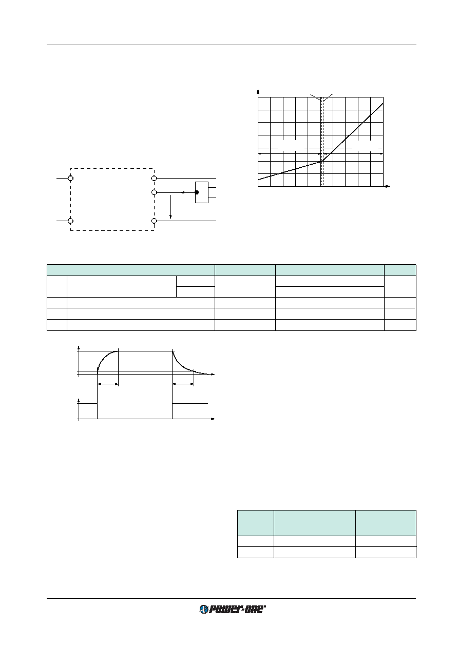
Table 5: Inhibit data
Characteristics
Conditions
min
typ
max
Unit
Uinh
Inhibit input voltage to keep
Uo = on
Ui min...Ui max
–50
0.8
V DC
output voltage
Uo = off
TC min...TC max
2.4
50
Iinh
Inhibit current
Uinh = 0
–400
A
t r
Rise time
30
ms
tf
Fall time
depending on
Io
Fig. 15
Typical output response as a function of inhibit control
0
t
0
Inhibit
1
0.1
Uo nom
Output
tr
tf
05073
Sense Lines
(Only for single output units 5.1 V, 12 V, 15 V, 24 V)
This feature enables for compensation of voltage drops
across the connector contacts and if necessary, across the
load lines. If the sense lines are connected at the load
rather than directly at the connector, the user should en-
sure that
Uo max (between Vo1+ and Vo1–) is not exceeded.
We recommend connecting the sense lines directly at the
female connector.
For further information, please refer to:
Application Notes.
To ensure correct operation, both sense lines (S+ and S–)
should be connected to their respective power outputs
(Vo1+ and Vo1–)and the voltage difference between any
sense line and its respective power output pin (as meas-
ured on the connector) should not exceed the following val-
ues:
Note: The output terminals Vo1+ and Vo1- must always be
connected to the load before connecting the sense lines S+
and S–, otherwise the unit will be damaged.
Table 6: Maximum Voltage compensation allowed using
sense lines
Output
Total voltage difference
Voltage difference
voltage
between sense lines and
between
their respective outputs
Vo– and S–
5.1 V
< 0.5 V
< 0.25 V
12 V, 15 V
< 1.0 V
< 0.25 V
If the output voltages are increased above
Uo nom via R-in-
put control, option P setting, remote sensing or option T, the
output currents must be reduced accordingly so that
Po nom is not exceeded.
Auxiliary Functions
i Inhibit for Remote On and Off
Note: With open i input: Output is disabled (
Uo = off).
The outputs of the module may be enabled or disabled by
means of a logic signal (TTL, CMOS, etc.) applied between
the inhibit input i and the negative pin of output 1 (Vo1–). In
systems with several units, this feature can be used, for ex-
ample, to control the activation sequence of the converters.
If the inhibit function is not required, connect the inhibit pin
18 to pin 14 to enable the outputs (active low logic, fail
safe). For output response refer to:
Hold-up Time and Out-
put Response.
Vi+
Vi–
Vo–
i
Vo+
Iinh
Uinh
06031
1.6
0.8
0
–0.8
–50
Uinh [V]
Iinh [mA]
–30
0
–10
10
30
50
2.0
1.2
0.4
–0.4
Uinh = 0.8 V
Uo = on
Uo = off
Uinh = 2.4 V
06032
Fig. 13
Definition of Uinh and Iinh.
Fig. 14
Typical inhibit current Iinh versus inhibit voltage Uinh
相关PDF资料 |
PDF描述 |
|---|---|
| FS2660-7EPD1TB1 | 2-OUTPUT 100 W DC-DC REG PWR SUPPLY MODULE |
| FS2660-7RD0B2 | 2-OUTPUT 100 W DC-DC REG PWR SUPPLY MODULE |
| FS2660-7R | 2-OUTPUT 100 W DC-DC REG PWR SUPPLY MODULE |
| FS2660-9EPD7TB1 | 2-OUTPUT 100 W DC-DC REG PWR SUPPLY MODULE |
| FS2660-9EPD9TB1 | 2-OUTPUT 100 W DC-DC REG PWR SUPPLY MODULE |
相关代理商/技术参数 |
参数描述 |
|---|---|
| FS25R06KF | 制造商:未知厂家 制造商全称:未知厂家 功能描述:TRANSISTOR | IGBT POWER MODULE | 3-PH BRIDGE | 600V V(BR)CES | 25A I(C) |
| FS25R06KF2 | 制造商:未知厂家 制造商全称:未知厂家 功能描述:TRANSISTOR | IGBT POWER MODULE | 3-PH BRIDGE | 600V V(BR)CES | 25A I(C) |
| FS25R10KF2 | 制造商:未知厂家 制造商全称:未知厂家 功能描述:TRANSISTOR | IGBT POWER MODULE | 3-PH BRIDGE | 1KV V(BR)CES | 25A I(C) |
| FS25R12KE3G | 功能描述:IGBT 模块 N-CH 1.2KV 40A RoHS:否 制造商:Infineon Technologies 产品:IGBT Silicon Modules 配置:Dual 集电极—发射极最大电压 VCEO:600 V 集电极—射极饱和电压:1.95 V 在25 C的连续集电极电流:230 A 栅极—射极漏泄电流:400 nA 功率耗散:445 W 最大工作温度:+ 125 C 封装 / 箱体:34MM 封装: |
| FS25R12KF | 制造商:未知厂家 制造商全称:未知厂家 功能描述:TRANSISTOR | IGBT POWER MODULE | 3-PH BRIDGE | 1.2KV V(BR)CES | 25A I(C) |
发布紧急采购,3分钟左右您将得到回复。