- 您现在的位置:买卖IC网 > PDF目录67594 > G1427F31UF (Global Mixed-mode Technology Inc.) 2W Stereo Audio Amplifier PDF资料下载
参数资料
| 型号: | G1427F31UF |
| 厂商: | Global Mixed-mode Technology Inc. |
| 元件分类: | 音频放大器 |
| 英文描述: | 2W Stereo Audio Amplifier |
| 中文描述: | 2W立体声音频放大器 |
| 文件页数: | 5/16页 |
| 文件大小: | 346K |
| 代理商: | G1427F31UF |
Ver: 1.3
Sep 23, 2005
TEL: 886-3-5788833
http://www.gmt.com.tw
13
G1427
Global Mixed-mode Technology Inc.
Application Information
Gain setting via GAIN0 and GAIN1 inputs
The internal gain setting is determined by two input
terminals, GAIN0 and GAIN1. The gains listed in Table
1 are realized by changing the taps on the input resis-
tors inside the amplifier. This will cause the internal
input impedance, ZI, to be dependent on the gain set-
ting. Although the real input impedance will shift by
30% due to process variation from part-to-part, the
actual gain settings are controlled by the ratios of the
resistors and the actual gain distribution from part-to-
part is quite good.
Table 1
GAIN0
GAIN1
SE/
BTL
AV (dB)
0
6
0
1
0
10
1
0
15.6
1
0
21.6
X
1
4.1
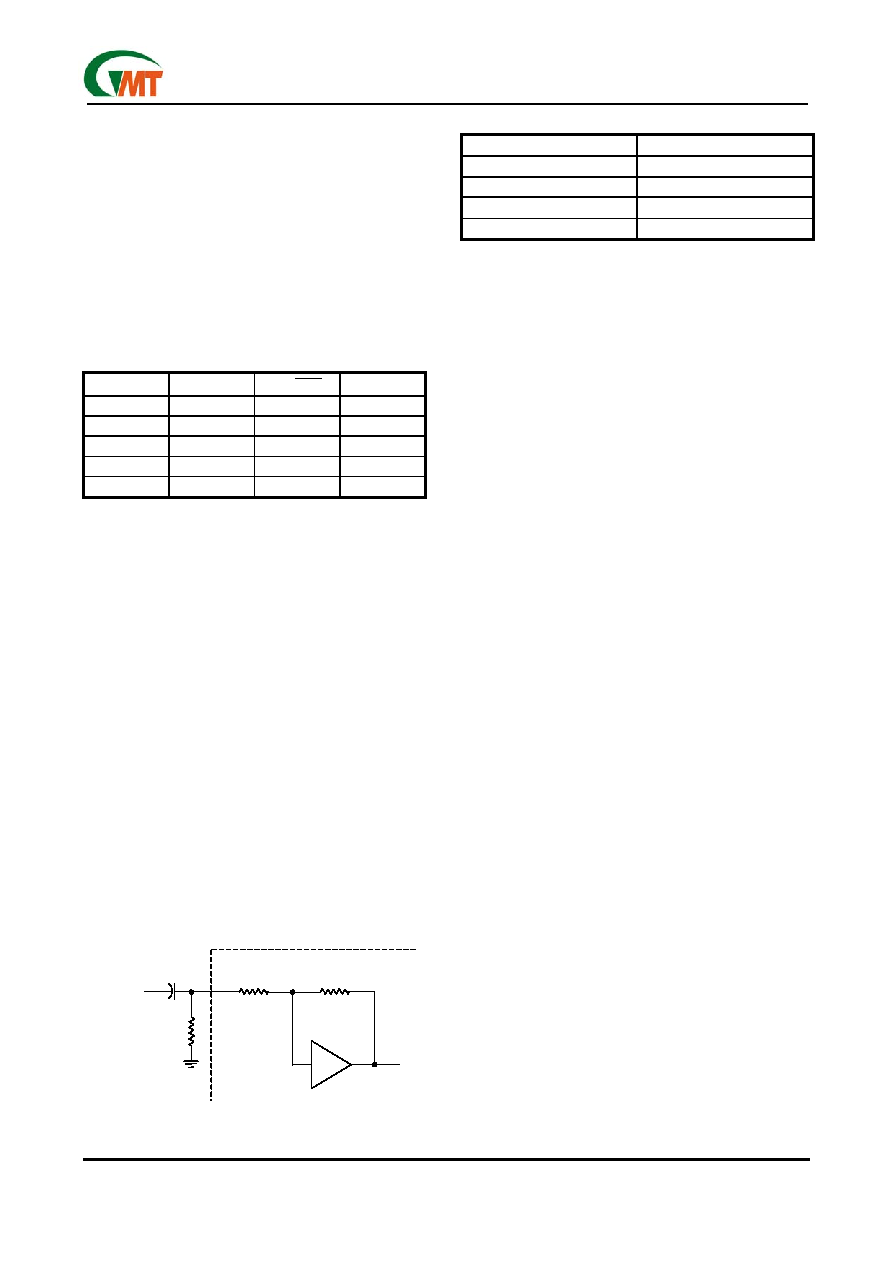
Input Resistance
The typical input impedance at each gain setting is given
in the Table 2. Each gain setting is achieved by varying
the input resistance of the amplifier, which can be over 3
times from its minimum value to the maximum value. As
a result, if a single capacitor is used in the input high
pass filter, the -3dB or cut-off frequency will be also
change over 3 times. To reduce the variation of the
cut-off frequency, an additional resistor can be con-
nected from the input pin of the amplifier to the ground,
as shown in Figure 1. With the extra resistor, the cut-off
frequency can be re-calculated using equation : f-3dB= 1/
2πC(R||RI). Using small external R can reduce the varia-
tion of the cut-off frequency. But the side effect is small
external R will also let (R||RI) become small, the cut-off
frequency will be larger and degraded the bass-band
performance. The other side effect is with extra power
dissipation through the external resistor R to the ground.
So using the external resistor R to flatting the variation of
the cut-off frequency, the user must also consider the
bass-band performance and the extra power dissipation
to choose the accepted external resistor R value.
Table 2
Zi (Kohm)
AV (dB)
30
21.6
45
15.6
70
10
90
6
Input Capacitor
In the typical application, an input capacitor Ci is re-
quired to allow the amplifier to bias the input signal to
the proper dc level for optimum operation. In this
case ,Ci and the input impedance of the amplifier, Zi,
form a high-pass filter with the -3dB determined by the
equation: f-3dB= 1/ (2πRI Ci)
The value of Ci is important to consider as it directly af-
fects the bass performance of the application circuit. For
example, if the input resistor is 15k
Ω, the input capacitor
is 1F, the flat bass response will be down to 10.6Hz.
Because the small leakage current of the input capaci-
tors will cause the dc offset voltage at the input to the
amplifier that reduces the operation headroom, espe-
cially at the high gain applications. The low-leakage
tantalum or ceramic capacitors are suggested to be
used as the input coupling capacitors. When using the
polarized capacitors, it is important to let the positive
side connecting to the higher dc level of the application.
Power Supply Decoupling
The G1427 is a high-performance CMOS audio ampli-
fier that requires adequate power supply decoupling to
make sure the output total harmonic distortion (THD)
as low as possible. The optimum decoupling is using
two capacitors with different types that target different
types of noise on the power supply leads. For high
frequency transients, spikes, a good low ESR ceramic
capacitor works best, typically 0.1F/1F used and
placed as close as possible to the G1427 VDD lead. A
larger aluminum electrolytic capacitor of 10F or
greater placed near the device power is recommended
for filtering low-frequency noise.
Optimizing DEPOP Operation
Circuitry has been implemented in G1427 to mini-
mize the amount of popping heard at power-up and
when coming out of shutdown mode. Popping oc-
curs whenever a voltage step is applied to the
speaker and making the differential voltage gener-
ated at the two ends of the speaker. To avoid the
popping heard, the bypass capacitor should be
chosen promptly, 1/(CBx170kΩ) ≦ 1/(CI*(RI+RF)).
Input Signal
C
R
IN
Zi
Zf
Figure 1
Input Signal
C
R
IN
Zi
Zf
Input Signal
C
R
IN
Zi
Zf
Figure 1
相关PDF资料 |
PDF描述 |
|---|---|
| G1427F31U | 2W Stereo Audio Amplifier |
| G1427 | 2W Stereo Audio Amplifier |
| G1428 | 2W Stereo Audio Amplifier |
| G1428F31U | 2W Stereo Audio Amplifier |
| G1428F31UF | 2W Stereo Audio Amplifier |
相关代理商/技术参数 |
参数描述 |
|---|---|
| G1428 | 制造商:GMT 制造商全称:Global Mixed-mode Technology Inc 功能描述:2W Stereo Audio Amplifier |
| G1428F31U | 制造商:GMT 制造商全称:Global Mixed-mode Technology Inc 功能描述:2W Stereo Audio Amplifier |
| G1428F31UF | 制造商:GMT 制造商全称:Global Mixed-mode Technology Inc 功能描述:2W Stereo Audio Amplifier |
| G1430 | 制造商:GMT 制造商全称:Global Mixed-mode Technology Inc 功能描述:2W Stereo Audio Amplifier |
| G1430Z4T | 制造商:GMT 制造商全称:Global Mixed-mode Technology Inc 功能描述:2W Stereo Audio Amplifier |
发布紧急采购,3分钟左右您将得到回复。