- 您现在的位置:买卖IC网 > PDF目录173375 > G3PC-220B-VD TRANSISTOR OUTPUT SOLID STATE RELAY, 2500 V ISOLATION-MAX PDF资料下载
参数资料
| 型号: | G3PC-220B-VD |
| 元件分类: | 继电器,输入/输出模块 |
| 英文描述: | TRANSISTOR OUTPUT SOLID STATE RELAY, 2500 V ISOLATION-MAX |
| 文件页数: | 3/7页 |
| 文件大小: | 658K |
| 代理商: | G3PC-220B-VD |
G3PC
3
Operation
■ Failure Detection Function
Conditions for SSR Failure Detection
Note: 1. The contents of each of the above failure modes is as follows:
SSR short-circuit: SSR output circuit remains in the ON state.
SSR half-wave short-circuit: SSR output circuit remains in the ON state in one direction.
SSR open-circuit: SSR output circuit remains in the OFF state.
SSR half-wave open-circuit: SSR output circuit remains in the OFF state in one direction.
In addition to the failure modes listed above, detection of circuit disconnections for the load circuit is also possible. (As a rough guide,
circuit disconnection will be detected if the load impedance is greater than or equal to 1 M
Ω.)
2. The same power supply is used for both the detection and for the output circuit and so detection is not performed during power
interruptions.
3. If power supply (terminal 3) is in the open state, the SSR will still turn ON and OFF in the same way but the failure detection function and
alarm display will not operate properly.
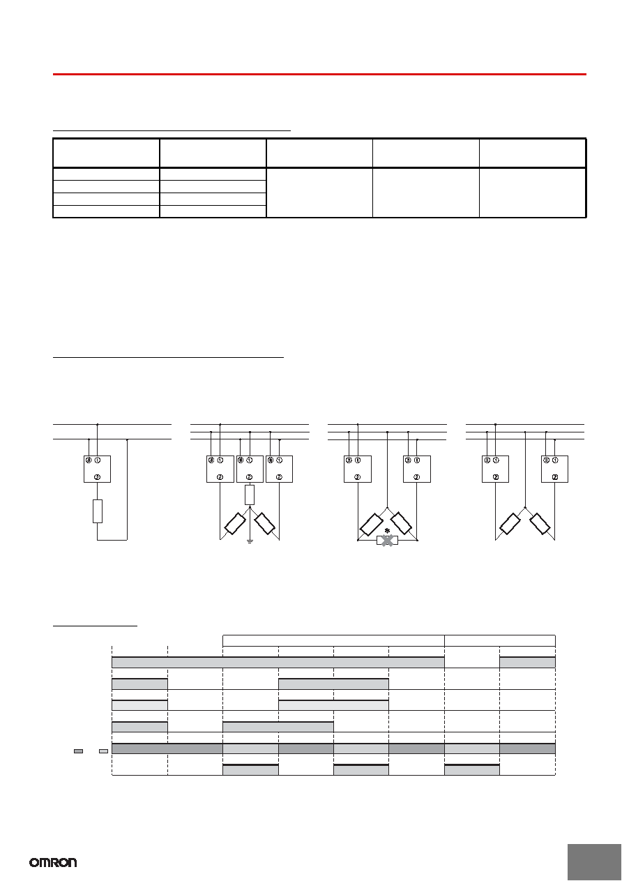
Connection Diagrams (Main Circuit)
The following diagrams show the applicable load connection configurations for SSR failure detection.
Note: 1. With 3-phase connection, so that the power supply voltage is applied between the G3PC’s terminals 1/L1 and 3, connect the desired
phase to terminal 3.
2. When grounding to a neutral point with a three-phase start connection, an overvoltage will be applied to the G3PC if the neutral point
becomes disconnected, possibly causing product failure. Make sure the connection to the neutral point is secure.
3. Detection is not possible for the heater indicated with an asterisks with a three-phase delta connection.
Timing Chart
Note: After failure detection, if the detection conditions differ to the conditions given under Conditions for SSR Failure Detection, alarm output is
reset.
Failure mode
(See note 1.)
Operating input (between
terminals A1 and A2)
Detection time
Alarm display
(See note 3.)
Alarm display (between
terminals X1 and X2)
(See note 3.)
SSR short-circuit
OFF
0.5 s max. (See note 2.)
Red
Open collector transistor
output
SSR half-wave short-circuit OFF
SSR open-circuit
ON
SSR half-wave open-circuit ON
Single Phase
3-phase Star
Connection
3-phase Delta
Connection (3-phase,
2-wire Switching)
3-phase V
Connection
G3PC
Heater
Main circuit power
supply (load side)
Operating input
(between terminals
A1 and A2)
Input LED
(yellow)
Load current
RDY/ALM LED
(Green:
; Red:
)
Alarm output
(between terminals
X1 and X2)
SSR ON normally
SSR OFF normally
SSR short-circuit
Reset (See note.)
SSR open-circuit
Reset (See note.)
SSR failure detection
Circuit disconnection detection on the load side
Load circuit disconnection
Reset (See note.)
相关PDF资料 |
PDF描述 |
|---|---|
| G3TA-IDZR02SM-USDC4-24 | TRANSISTOR OUTPUT SOLID STATE RELAY, 4000 V ISOLATION-MAX |
| G3TB-OD201P-US | TRANSISTOR OUTPUT SOLID STATE RELAY, 4000 V ISOLATION-MAX |
| G3VM-22FO(TR) | TRANSISTOR OUTPUT SOLID STATE RELAY, 2500 V ISOLATION-MAX |
| G3VM-352F | DUAL TRANSISTOR OUTPUT SOLID STATE RELAY, 2500 V ISOLATION-MAX |
| G572A | 50 A, 75 V, NPN, Si, POWER TRANSISTOR |
相关代理商/技术参数 |
参数描述 |
|---|---|
| G3PC-220B-VD DC12-24 | 功能描述:固态继电器-工业安装 SOLID STATE RELAY W/ DETECTOR RoHS:否 制造商:Crydom 控制电压范围:4 VDC to 32 VDC 负载电压额定值:7 VDC to 72 VDC 负载电流额定值:160 A 触点形式: 输出设备:SSR 安装风格:Panel |
| G3PC220BVDDC1224 | 制造商:OMRON AUTOMATION AND SAFETY 功能描述:RELAY SSR W/DETECTR 20A 100-240V 制造商:OMRON INDUSTRIAL AUTOMATION 功能描述:SOLID STATE RELAY W/ DETECTOR |
| G3PE | 制造商:OMRON 制造商全称:Omron Electronics LLC 功能描述:Single-phase Solid State Relays for Heaters |
| G3PE-215B | 制造商:OMRON 制造商全称:Omron Electronics LLC 功能描述:Single-phase Solid State Relays for Heaters |
| G3PE-215B DC12-24 | 功能描述:固态继电器-工业安装 Solid State Contactor RoHS:否 制造商:Crydom 控制电压范围:4 VDC to 32 VDC 负载电压额定值:7 VDC to 72 VDC 负载电流额定值:160 A 触点形式: 输出设备:SSR 安装风格:Panel |
发布紧急采购,3分钟左右您将得到回复。