- 您现在的位置:买卖IC网 > PDF目录64947 > G5111T11UF (Global Mixed-mode Technology Inc.) Micro-power Step-Up DC/DC Converters in SOT-23-5 PDF资料下载
参数资料
| 型号: | G5111T11UF |
| 厂商: | Global Mixed-mode Technology Inc. |
| 英文描述: | Micro-power Step-Up DC/DC Converters in SOT-23-5 |
| 中文描述: | 微功率升压型DC / DC转换器采用SOT - 23 - 5 |
| 文件页数: | 5/8页 |
| 文件大小: | 432K |
| 代理商: | G5111T11UF |
Ver: 1.2
Sep 09, 2004
TEL: 886-3-5788833
http://www.gmt.com.tw
5
G5111
Global Mixed-mode Technology Inc.
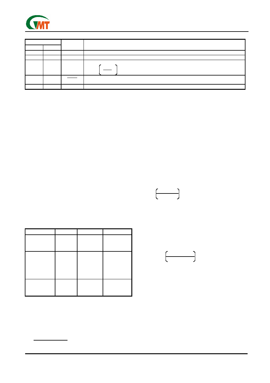
Pin Description
PIN
T11
T12
NAME
FUNCTION
1
4
SW
Switch Pin. The drain of the internal NMOS power switch. Connect this pin to inductor.
2
3
GND
Ground.
3
5
FB
Feedback Pin. Set the output voltage by selecting values for R1 and R2 (see Block Diagram):
R1 = R2
2
.
1
VOUT
-1
4
1
SHDN
Active-Low Shutdown Pin. Tie this pin to logic-high to enable the device or tied it to logic-low
to turn this device off.
5
2
VCC
Input Supply Pin. Bypass this pin with a capacitor as close to the device as possible.
Function Description
The G5111 is a boost converter with a NMOS switch
embedded (refer to Block Diagram). The boost cycle
is getting started when FB pin voltage drop below
1.2V as the NMOS switch turns on. During the switch
on period, the inductor current ramps up until 350mA
current limit is reached. Then turns the switch off,
while the inductor current flows through external
schottky diode, and ramps down to zero. During the
switch off period, the inductor current charges output
capacitor and the output voltage is boosted up. This
pumping mechanism continues cycle by cycle until
the FB pin voltage exceed 1.2V and entering the none
switching mode. In this mode, the G5111 consumes
as low as 20A typically to save battery power.
Applications Information
Choosing an Inductor
There are several recommended inductors that work
well with the G5111 in Table 1. Use the equations and
recommendations in the next few sections to find the
proper inductance value for your design.
Table 1. Recommended Inductors
PART
VALUE
(H) MAX DCR ()
VENDOR
LQH3C4R7
LQH3C100
LQH3C220
4.7
10
22
0.26
0.30
0.92
Murata
www.murata.com
CD43-4R7
CD43-100
CDRH4D18-4R
7
CDRH4D18-100
4.7
10
4.7
10
0.11
0.18
0.16
0.20
Sumida
www.sumida.com
DO1608-472
DO1608-103
DO1608-223
4.7
10
22
0.09
0.16
0.37
Coilcraft
www.coilcraft.com
Inductor Selection—Boost Regulator
The appropriate inductance value for the boost regu-
lator application may be calculated from the following
equation. Select a standard inductor close to this
value.
VOUT-VIN(MIN)+VD
L =
ILIM
x tOFF
Where VD = 0.4V (Schottky diode voltage), ILIM =
350mA and tOFF = 500ns. A larger value can be used
to lightly increase the available output current, but limit
it to about twice the calculating value. When too large
of an inductor will increase the output voltage ripple
without providing much additional output current. In
varying VIN condition such as battery power applica-
tions, use the minimum VIN value in the above equa-
tion. A smaller value can be used to give smaller
physical size, but the inductor current overshoot will be
occurs (see Current Limit Overshoot section).
Inductor Selection—SEPIC Regulator
For a SEPIC regulator using the G5111, the approxi-
mate inductance value can be calculated by below
formula. As for the boost inductor selection, a larger or
smaller value can be used.
VOUT + VD
L = 2
ILIM
x tOFF
Current Limit Overshoot
The G5111 use a constant off-time control scheme,
the power switch is turned off after the 350mA current
limit is reached. When the current limit is reached and
when the switch actually turns off, there is a 100ns
delay time. During this time, the inductor current ex-
ceeds the current limit by a small amount. The formula
below can calculate the peak inductor current.
VIN(MAX) - VSAT
IPEAK = ILIM +
L
x 100ns
Where VSAT = 0.25V (switch saturation voltage). When
the systems with high input voltages and uses smaller
inductance value, the current overshoot will be most
apparent. This overshoot can be useful as it helps in-
crease the amount of available output current. To use
small inductance value for systems design, the current
limit overshoot can be quite high. Even if it is internally
current limited to 350mA, the power switch of the
G5111 can operate larger currents without any prob-
lem, but the total efficiency will suffer. The IPEAK is keep
below 500mA for the G5111 will be obtained best per-
formance.
相关PDF资料 |
PDF描述 |
|---|---|
| G5111T11U | Micro-power Step-Up DC/DC Converters in SOT-23-5 |
| G5111T12UF | Micro-power Step-Up DC/DC Converters in SOT-23-5 |
| G5111T12U | Micro-power Step-Up DC/DC Converters in SOT-23-5 |
| G5121TB1U | Fixed Frequency White LED Step-Up Converter |
| G5121TP1U | Fixed Frequency White LED Step-Up Converter |
相关代理商/技术参数 |
参数描述 |
|---|---|
| G5111T12U | 制造商:GMT 制造商全称:Global Mixed-mode Technology Inc 功能描述:Micro-power Step-Up DC/DC Converters in SOT-23-5 |
| G5111T12UF | 制造商:GMT 制造商全称:Global Mixed-mode Technology Inc 功能描述:Micro-power Step-Up DC/DC Converters in SOT-23-5 |
| G5113 | 制造商:未知厂家 制造商全称:未知厂家 功能描述:Micro-power Step-Up DC/DC Converters in SOT23-5 |
| G51130361000005 | 制造商:Promise Technologies 功能描述:CABLE.MINI SAS.100CM.MINI SAS - Bulk |
| G5114 | 制造商:GMT 制造商全称:Global Mixed-mode Technology Inc 功能描述:High Efficiency, Constant Current Output for 8 Series LEDs Driver |
发布紧急采购,3分钟左右您将得到回复。