- 您现在的位置:买卖IC网 > PDF目录7855 > G6J-2FS-Y DC5 (Omron Electronics Inc-EMC Div)RELAY TELECOM DPDT 1A 5V PDF资料下载
参数资料
| 型号: | G6J-2FS-Y DC5 |
| 厂商: | Omron Electronics Inc-EMC Div |
| 文件页数: | 10/12页 |
| 文件大小: | 0K |
| 描述: | RELAY TELECOM DPDT 1A 5V |
| 产品培训模块: | Medical Solutions |
| 产品目录绘图: | G6J(U)-2(FL,FS) Series G6J(U)-FS Series Footprint G6J-2(FL,FS)-Y Series Circuit Top View |
| 标准包装: | 50 |
| 系列: | G6J-Y |
| 继电器类型: | 电信 |
| 线圈类型: | 无锁存 |
| 线圈电流: | 28.9mA |
| 线圈电压: | 5VDC |
| 触点形式: | DPDT(2 C 型) |
| 触点额定值(电流): | 1A |
| 切换电压: | 125VAC,110VDC - 最小值 |
| 关闭电压(最大): | 3.75 VDC |
| 关闭电压(最小): | 0.5 VDC |
| 安装类型: | 表面贴装 |
| 端接类型: | 鸥翼型 |
| 包装: | 管件 |
| 触点材料: | Silver(Ag),Gold(Au) |
| 操作时间: | 3ms |
| 释放时间: | 3ms |
| 线圈功率: | 140 mW |
| 线圈电阻: | 173.1 欧姆 |
| 工作温度: | -40°C ~ 85°C |
| 产品目录页面: | 2588 (CN2011-ZH PDF) |
| 其它名称: | G6J 3004C G6J-2FS-Y-DC5 G6J2FSY5DC G6J2FSYDC5 Z2136 |
�� �
�
�Precautions�
�Correct� Use�
�Long� Term� Current� Carrying�
�Under� a� long-term� current� carrying� without� switching,� the� insulation�
�resistance� of� the� coil� goes� down� gradually� due� to� the� heat� generated�
�b� y� the� coil� itself.� Furthermore,� the� contact� resistance� of� the� Relay� will�
�gradually� b� ecome� unsta� b� le� due� to� the� generation� of� film� on� the� con-�
�tact� surfaces.� A� Latching� Relay� can� b� e� used� to� prevent� these� pro� b� -�
�lems.� When� using� a� non-latching� relay,� the� design� of� the� fail-safe�
�circuit� provides� protection� against� contact� failure� and� open� coils.�
�Handling� of� Surface-mounting� Relays�
�Use� the� Relay� as� soon� as� possi� b� le� after� opening� the� moisture-proof�
�package.� If� the� Relay� is� left� for� a� long� time� after� opening� the� mois-�
�ture-proof� package,� the� appearance� may� suffer� and� seal� failure� may�
�occur� after� the� solder� mounting� process.� To� store� the� Relay� after�
�opening� the� moisture-proof� package,� place� it� into� the� original� pack-�
�age� and� seal� the� package� with� adhesive� tape.�
�When� washing� the� product� after� soldering� the� Relay� to� a� PCB,� use� a�
�water-� b� ased� solvent� or� alcohol-� b� ased� solvent,� and� keep� the� solvent�
�temperature� at� less� than� 40� °� C.� Do� not� put� the� relay� in� a� cold� cleaning�
�b� ath� immediately� after� soldering.�
�Soldering�
�Solder:� JIS� Z3282,� H63A�
�Soldering� temperature:� Approx.� 250°C� (At� 260°C� if� the� DWS� method�
�is� used.)�
�Soldering� time:� Approx.� 5� s� max.� (Approx.� 2� s� for� the� first� time� and�
�approx.� 3� s� for� the� second� time� if� the� DWS� method� is� used.)�
�Be� sure� to� adjust� the� level� of� the� molten� solder� so� that� the� solder� will�
�not� overflow� onto� the� PCB.�
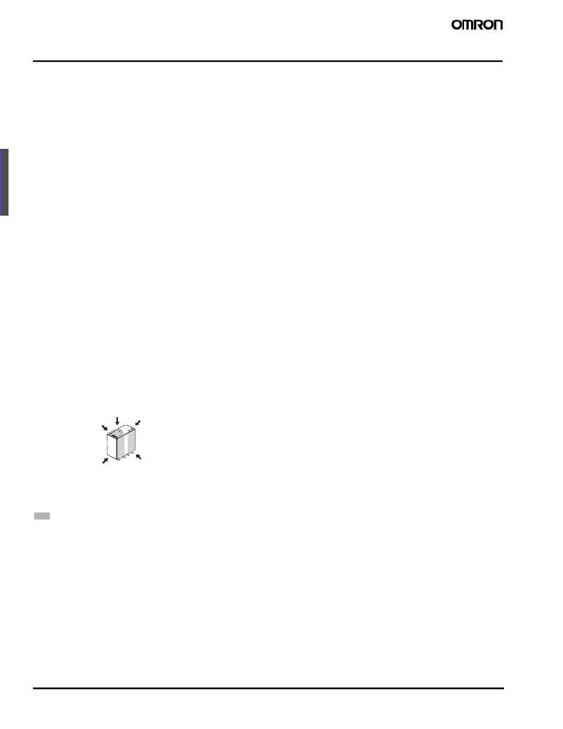
�Claw� Securing� Force� During� Automatic� Insertion�
�During� automatic� insertion� of� Relays,� make� sure� to� set� the� securing�
�force� of� the� claws� to� the� following� values� so� that� the� Relay� character-�
�istics� will� b� e� maintained.�
�Maximum� Voltage�
�The� maximum� voltage� of� the� coil� can� b� e� o� b� tained� from� the� coil� tem-�
�perature� increase� and� the� heat-resisting� temperature� of� coil� insulat-�
�ing� sheath� material.� (Exceeding� the� heat-resisting� temperature� may�
�result� in� b� urning� or� short-circuiting.)� The� maximum� voltage� also�
�involves� important� restrictions.� Maximum� voltage:�
�?� must� not� cause� thermal� changes� or� deterioration� of� the� insulating�
�material.�
�?� must� not� cause� damage� to� other� control� devices.�
�?� must� not� cause� any� harmful� effect� on� people.�
�?� must� not� cause� fire.�
�Therefore,� b� e� sure� not� to� exceed� the� maximum� voltage� specified� in�
�the� catalog.�
�As� a� rule,� the� rated� voltage� must� b� e� applied� to� the� coil.� A� voltage�
�exceeding� the� rated� value,� however,� can� b� e� applied� to� the� coil� pro-�
�vided� that� the� voltage� is� less� than� the� maximum� voltage.� It� must� b� e�
�noted� that� continuous� voltage� application� to� the� coil� will� cause� a� coil�
�temperature� increase� which� could� deteriorate� the� coil� insulation,�
�shorten� the� relay’s� electrical� life,� or� affect� various� characteristics� of�
�the� relay.�
�Coating�
�Relays� mounted� on� PCBs� may� b� e� coated� or� washed.� Do� not� apply�
�coatings� or� detergents� containing� silicone.�
�Other� Handling�
�Dropping� the� relay� may� impose� excess� shock� that� exceeds� the� spec-�
�ifications.� Do� not� use� any� relay� that� has� b� een� dropped.�
�C�
�B�
�A�
�Direction� A:� 4.90� N� max.�
�Direction� B:� 9.80� N� max.�
�Direction� C:� 9.80� N� max.�
�Secure� the� claws� to� the� area� indicated� b� y� shading.�
�Do� not� attach� them� to� the� center� area� or� to� only� part� of� the� Relay.�
�Environmental� Conditions� During� Operation,� Storage,�
�and� Transportation�
�Protect� the� Relays� from� direct� sunlight� and� keep� the� Relays� under�
�normal� temperature,� humidity,� and� pressure.�
�Mounting� Latching� Relays�
�The� Latching� Relays� are� reset� b� efore� shipping.� If� excessive� vi� b� ration�
�or� shock� is� imposed,� however,� the� Latching� Relays� may� b� e� set� acci-�
�dentally.� Be� sure� to� apply� a� reset� signal� b� efore� use.� Make� sure� that�
�the� vi� b� ration� or� shock� that� is� generated� b� y� other� devices� on� the� same�
�panel� does� not� exceed� the� rated� value� of� the� Latching� Relays.�
�52�
�Surface-mounting� Relay�
�G6J-Y�
�相关PDF资料 |
PDF描述 |
|---|---|
| 0395132309 | 3.81MM EURO PLUG STR BLK 9POS |
| DRA3P48D4 | RELAY CONT 3PH 480VAC 4A 5VDC |
| 0395105210 | 3.81MM EURO PLUG RA GRN 10POS |
| 25MM-25MM-10-8815 | TAPE ADHESIVE TRANSFER 22X25MM |
| DC100D10C | RELAY SSR 100VDC/10A 4-32VDC |
相关代理商/技术参数 |
参数描述 |
|---|---|
| G6J-2FSY-DC5 | 制造商:OMRON Electronic Components LLC 功能描述: |
| G6J-2FS-Y-TR DC12 | 功能描述:RELAY TELECOM DPDT 1A 12V RoHS:是 类别:继电器 >> 信号,高达 2 A 系列:G6J-Y 产品目录绘图:8000 Series 8000 Series Footprint 8002, 8L02, 8L61 Circuit 标准包装:25 系列:8L 继电器类型:舌簧 线圈类型:无锁存 线圈电流:12mA 线圈电压:24VDC 触点形式:DPST(2 A 型) 触点额定值(电流):500mA 切换电压:200VAC,200VDC - 最小值 关闭电压(最大):19.2 VDC 关闭电压(最小):2 VDC 特点:二极管,带静电屏蔽 安装类型:通孔 端接类型:PC 引脚 包装:管件 触点材料:- 操作时间:0.5ms 释放时间:1ms 线圈功率:- 线圈电阻:2 千欧 工作温度:-20°C ~ 85°C 产品目录页面:2577 (CN2011-ZH PDF) 其它名称:306-1042 |
| G6J-2FS-Y-TR DC24 | 功能描述:低信号继电器 - PCB SMT Short Ld NoLatch DPDT 24DC 230mW T/R RoHS:否 制造商:NEC 触点形式:2 Form C (DPDT-BM) 触点电流额定值: 线圈电压:5 V 最大开关电流:1 A 线圈电流:1 A 线圈类型:Non-Latching 功耗:140 mW 端接类型:SMT 绝缘: 介入损耗: |
| G6J-2FS-Y-TR DC3 | 功能描述:低信号继电器 - PCB SMT Short Ld NoLatch DPDT 3VDC 140mW T/R RoHS:否 制造商:NEC 触点形式:2 Form C (DPDT-BM) 触点电流额定值: 线圈电压:5 V 最大开关电流:1 A 线圈电流:1 A 线圈类型:Non-Latching 功耗:140 mW 端接类型:SMT 绝缘: 介入损耗: |
| G6J-2FS-Y-TR DC4.5 | 功能描述:RELAY TELECOM DPDT 1A 4.5V RoHS:是 类别:继电器 >> 信号,高达 2 A 系列:G6J-Y 其它有关文件:Relay Technical Info Standards Chart 产品变化通告:AGQ Series Nominal Capacity Change 18/Jul/2011 标准包装:50 系列:AGQ 继电器类型:电信 线圈类型:锁存,单线圈 线圈电流:8.3mA 线圈电压:12VDC 触点形式:DPDT(2 C 型) 触点额定值(电流):2A 切换电压:125VAC,110VDC - 最小值 关闭电压(最大):9 VDC 关闭电压(最小):- 特点:- 安装类型:表面贴装 端接类型:鸥翼型 包装:管件 触点材料:银钯(AgPd),金(Au) 操作时间:4ms 释放时间:4ms 线圈功率:100 mW 线圈电阻:1.44 千欧 工作温度:-40°C ~ 85°C |
发布紧急采购,3分钟左右您将得到回复。