- 您现在的位置:买卖IC网 > PDF目录60605 > GNR07D201K (CERAMATE TECHNOLOGY CO., LTD.) VARISTOR PDF资料下载
参数资料
| 型号: | GNR07D201K |
| 厂商: | CERAMATE TECHNOLOGY CO., LTD. |
| 元件分类: | 压敏电阻 |
| 英文描述: | VARISTOR |
| 中文描述: | 压敏电阻 |
| 文件页数: | 4/5页 |
| 文件大小: | 61K |
| 代理商: | GNR07D201K |
TYPE
GNR07D□□□
□□□
□□□K
MODEL
PAGE
4/
5
CITATION
DATE
Oct. 13, 2001
SUBJECT
ELECTRICAL CHARACTERISTICS
REV.
B01
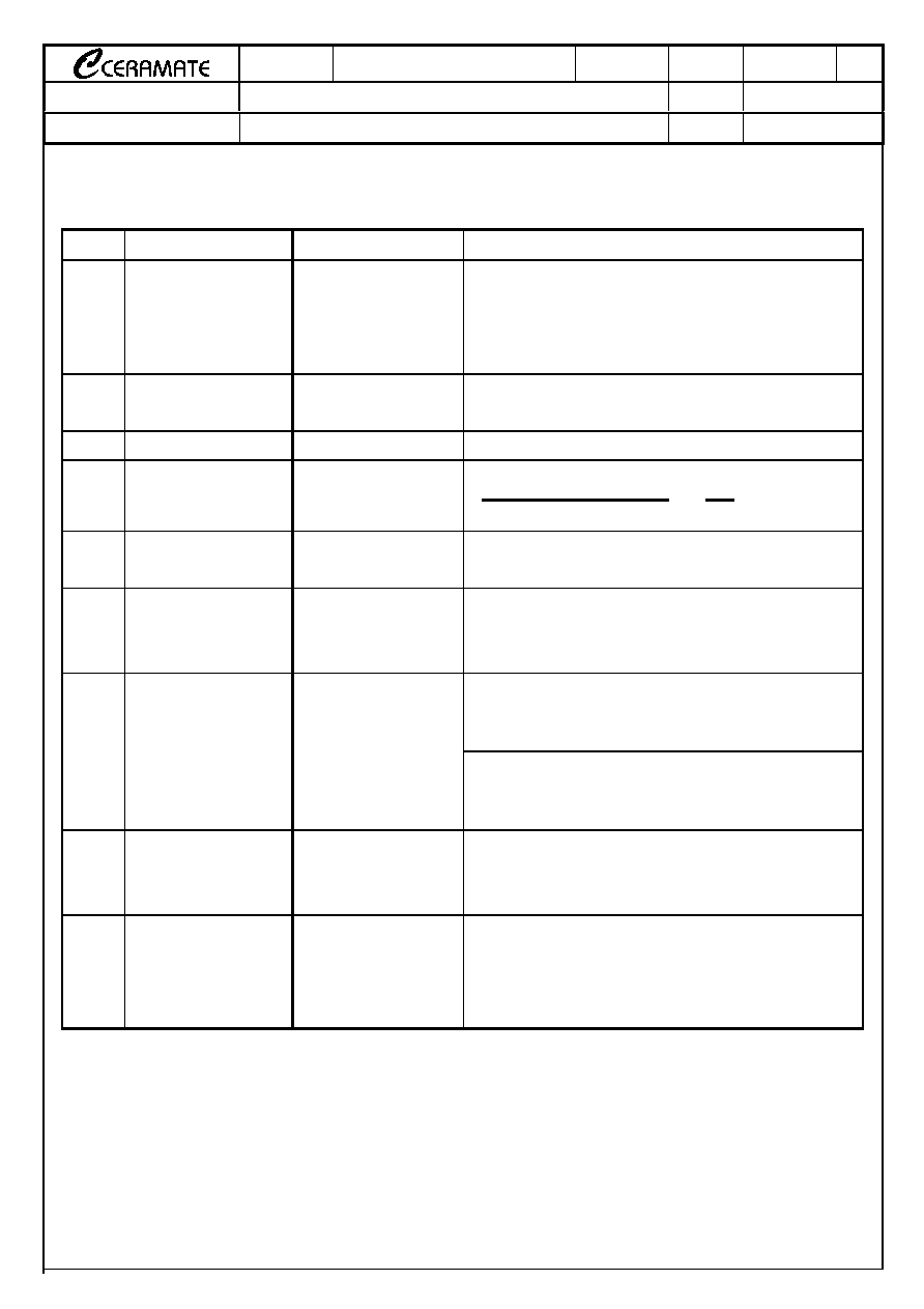
4. ELECTRICAL CHARACTERISTICS
N0.
ITEM
PERFORMANCE
TEST METHODS
4.0
Standard Conditions
Unless otherwise specified, all tests are made under
environmental conditions as given below:
Temperature:
535℃
Relative humidity:
4585 % RH
4.1
Maximum Allowable
Voltage
AC : *
*
*(2) Vrms
DC : *
*
*(2) V
Maximum continuous sine wave(RMS) or DC
voltage which may be applied.
4.2
Varistor Voltage
V1mA : *
*
*(2) V
Voltage across the varistor measured at CmA DC.
4.3
Varistor Voltage
Temperature
Coefficient
0
0.05 %/℃
VCmA at 85℃ - VCmA at 25℃
1
VCmA at 25℃
60
4.4
Max. Clamping
Voltage
*
*(2) V at *
*
*(2) A
Peak voltage across the varistor with a specified
peak impulse current of 8× 20μs waveform.
4.5
Rated Power
*
*(2) W
Maximum 5060Hz power which may be loaded
for 1,000 hrs at 85± 2℃ with △VCmA/ VCmA ≦±
10%.
The max. current within the varistor voltage change
of less than ± 10% when impulse current (8× 20μ
s) applied .
4.6
Withstanding Surge
Current
*
*(2) A
The max. current within the varistor voltage change
of less than ± 10% when impulse current (8× 20μ
s) applied two times with an interval of 5 minutes.
4.7
Energy
*
*(2) Joule
The max. energy absorbed with a varistor voltage
change of less than ± 10% when one impulse(10×
1000μs) is applied.
4.8
Surge Life
*
*(2) A
The max. current with a varistor voltage change of
less than ± 10% when 10,000 times impulse current
(8× 20μs) are applied at intervals of 20 seconds at
room temperature.
* (2) See Page 5
×
× 100
相关PDF资料 |
PDF描述 |
|---|---|
| GNR07DK | VARISTOR |
| GNR07D151K | VARISTOR |
| GNR07D181K | VARISTOR |
| GNR07D220K | VARISTOR |
| GNR07D221K | VARISTOR |
相关代理商/技术参数 |
参数描述 |
|---|---|
| GNR07D201K4 | 制造商:未知厂家 制造商全称:未知厂家 功能描述:Catalog number system |
| GNR07D201KA | 制造商:未知厂家 制造商全称:未知厂家 功能描述:Catalog number system |
| GNR07D201KC | 制造商:未知厂家 制造商全称:未知厂家 功能描述:Catalog number system |
| GNR07D201KR | 制造商:未知厂家 制造商全称:未知厂家 功能描述:Catalog number system |
| GNR07D201KT | 制造商:未知厂家 制造商全称:未知厂家 功能描述:Catalog number system |
发布紧急采购,3分钟左右您将得到回复。