- 您现在的位置:买卖IC网 > PDF目录385329 > GS8642Z72C-300 (GSI TECHNOLOGY) 72Mb Pipelined and Flow Through Synchronous NBT SRAM PDF资料下载
参数资料
| 型号: | GS8642Z72C-300 |
| 厂商: | GSI TECHNOLOGY |
| 元件分类: | DRAM |
| 英文描述: | 72Mb Pipelined and Flow Through Synchronous NBT SRAM |
| 中文描述: | 1M X 72 ZBT SRAM, 5.5 ns, PBGA209 |
| 封装: | 22 X 14 MM, 1 MM PITCH, BGA-209 |
| 文件页数: | 26/34页 |
| 文件大小: | 872K |
| 代理商: | GS8642Z72C-300 |
第1页第2页第3页第4页第5页第6页第7页第8页第9页第10页第11页第12页第13页第14页第15页第16页第17页第18页第19页第20页第21页第22页第23页第24页第25页当前第26页第27页第28页第29页第30页第31页第32页第33页第34页
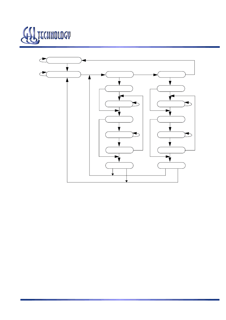
Select DR
Capture DR
0
Shift DR
Exit1 DR
Pause DR
Exit2 DR
Update DR
1
Select IR
Capture IR
0
Shift IR
Exit1 IR
Pause IR
Exit2 IR
Update IR
1
Test Logic Reset
Run Test Idle
0
1
0
1
1
0
1
1
1
0
0
1
1
0
0
0
0
1
1
0
0
0
0
0
1
1
1
1
Product Preview
GS8642Z18(B)/GS8642Z36(B)/GS8642Z72(C)
Specifications cited are subject to change without notice. For latest documentation see http://www.gsitechnology.com.
Rev: 1.02 5/2005
26/34
2004, GSI Technology
JTAG Tap Controller State Diagram
Instruction Descriptions
BYPASS
When the BYPASS instruction is loaded in the Instruction Register the Bypass Register is placed between TDI and TDO. This
occurs when the TAP controller is moved to the Shift-DR state. This allows the board level scan path to be shortened to facili-
tate testing of other devices in the scan path.
SAMPLE/PRELOAD
SAMPLE/PRELOAD is a Standard 1149.1 mandatory public instruction. When the SAMPLE / PRELOAD instruction is
loaded in the Instruction Register, moving the TAP controller into the Capture-DR state loads the data in the RAMs input and
I/O buffers into the Boundary Scan Register. Boundary Scan Register locations are not associated with an input or I/O pin, and
are loaded with the default state identified in the Boundary Scan Chain table at the end of this section of the datasheet. Because
the RAM clock is independent from the TAP Clock (TCK) it is possible for the TAP to attempt to capture the I/O ring contents
while the input buffers are in transition (i.e. in a metastable state). Although allowing the TAP to sample metastable inputs will
not harm the device, repeatable results cannot be expected. RAM input signals must be stabilized for long enough to meet the
TAPs input data capture set-up plus hold time (tTS plus tTH). The RAMs clock inputs need not be paused for any other TAP
operation except capturing the I/O ring contents into the Boundary Scan Register. Moving the controller to Shift-DR state then
places the boundary scan register between the TDI and TDO pins.
EXTEST
EXTEST is an IEEE 1149.1 mandatory public instruction. It is to be executed whenever the instruction register is loaded with
all logic 0s. The EXTEST command does not block or override the RAM’s input pins; therefore, the RAM’s internal state is
still determined by its input pins.
相关PDF资料 |
PDF描述 |
|---|---|
| GS8642Z72C-300I | 72Mb Pipelined and Flow Through Synchronous NBT SRAM |
| GS8642Z72GC-167 | 72Mb Pipelined and Flow Through Synchronous NBT SRAM |
| GS8642Z72GC-167I | 72Mb Pipelined and Flow Through Synchronous NBT SRAM |
| GS8642Z72GC-200 | 72Mb Pipelined and Flow Through Synchronous NBT SRAM |
| GS8642Z72GC-200I | 72Mb Pipelined and Flow Through Synchronous NBT SRAM |
相关代理商/技术参数 |
参数描述 |
|---|---|
| GS8642Z72C-300I | 制造商:GSI 制造商全称:GSI Technology 功能描述:72Mb Pipelined and Flow Through Synchronous NBT SRAM |
| GS8642Z72GC-167 | 制造商:GSI 制造商全称:GSI Technology 功能描述:72Mb Pipelined and Flow Through Synchronous NBT SRAM |
| GS8642Z72GC-167I | 制造商:GSI 制造商全称:GSI Technology 功能描述:72Mb Pipelined and Flow Through Synchronous NBT SRAM |
| GS8642Z72GC-200 | 制造商:GSI 制造商全称:GSI Technology 功能描述:72Mb Pipelined and Flow Through Synchronous NBT SRAM |
| GS8642Z72GC-200I | 制造商:GSI 制造商全称:GSI Technology 功能描述:72Mb Pipelined and Flow Through Synchronous NBT SRAM |
发布紧急采购,3分钟左右您将得到回复。