- 您现在的位置:买卖IC网 > PDF目录223868 > HA4060-AL (COILCRAFT INC) SMPS TRANSFORMER PDF资料下载
参数资料
| 型号: | HA4060-AL |
| 厂商: | COILCRAFT INC |
| 元件分类: | 开关电源变压器 |
| 英文描述: | SMPS TRANSFORMER |
| 封装: | ROHS COMPLIANT |
| 文件页数: | 1/1页 |
| 文件大小: | 71K |
| 代理商: | HA4060-AL |
Coilcraft, Inc. 2010
Specifications subject to change without notice.
Please check our website for latest information.
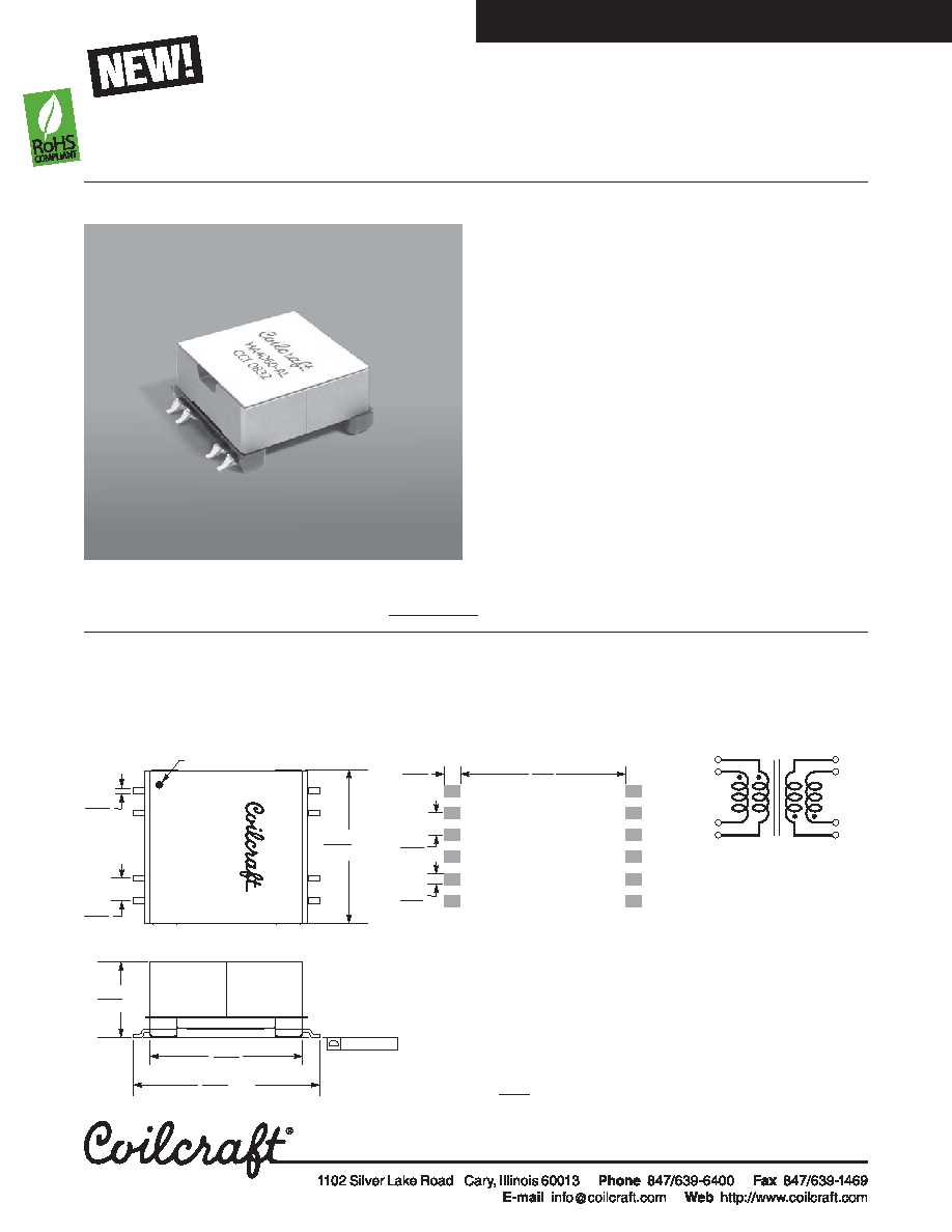
Flyback Transformer
Document 734
Revised 02/0909
1. Inductance is measured at 100 kHz, 0.1 Vrms.
2. Peak primary current drawn at minimum input voltage.
3. DCR is with the windings connected in parallel.
4. Leakage inductance is for both windings of the primary with the
secondary windings shorted.
Inductance
DCR max
Leakage
Volt-time
Part
at 0 A1
at Ipk2
(Ohms)3
inductance4
Turns ratio5
Ipk2
product
number
±10% (H)
min (H)
pri
sec
max (H)
pri : sec
(A)
typ (V sec)
HA4060-AL
300
270
0.422
1.58
2.7
1 : 3
2.0
600
Core material Ferrite
Terminations RoHS tin-silver over tin over nickel over phos
bronze. Other terminations available at additional cost.
Weight 23.8 g
Ambient temperature –40°C to +85°C
Storage temperature Component: –40°C to +85°C.
Packaging: –40°C to +80°C
Resistance to soldering heat Max three 40 second reflows at
+260°C, parts cooled to room temperature between cycles
Moisture Sensitivity Level (MSL) 1 (unlimited floor life at <30°C /
85% relative humidity)
Failures in Time (FIT) / Mean Time Between Failures (MTBF)
38 per billion hours / 26,315,789 hours, calculated per Telcordia SR-332
Packaging 24 per tray
PCB washing Only pure water or alcohol recommended
Flyback transformer for the Linear Technology LT3751
Capacitor Charger Controller
120 – 377 V input; up to 500 V output
3000 Vrms isolation from primary to secondary windings
Primary windings and secondary
windings to be connected in
parallel on PC board.
For Linear Technology LT3751
Capacitor Charger Controller
Dimensions are in
inches
mm
8
2
12
5
1
11
Pri
Sec
6
7
0.551
14,0
1.350
34,29
max
0.004 / 0,10
max
Recommended
Land Pattern
1.053
26,75
1.024
26,0
0.148
3,75
0.148
3,75
0.079
2,00
0.039
1,00
max
12
1
1.10
28,2
0.108
2,75
Dot indicates pin 1
12
HA4060-
AL
CCIxxxx
5. Turns ratios are with the primary and secondary windings connected in
parallel.
6. Electrical specifications at 25°C.
Refer to Doc 362 “Soldering Surface Mount Components” before soldering.
相关PDF资料 |
PDF描述 |
|---|---|
| HB-4V3216C-800JT | 4 FUNCTIONS, 0.2 A, FERRITE CHIP |
| HB-4V3216C-800JL | 4 FUNCTIONS, 0.2 A, FERRITE CHIP |
| HB-4V3216C-800JB | 4 FUNCTIONS, 0.2 A, FERRITE CHIP |
| HB-4V3216C-600JT | 4 FUNCTIONS, 0.2 A, FERRITE CHIP |
| HB-4V3216C-600JL | 4 FUNCTIONS, 0.2 A, FERRITE CHIP |
相关代理商/技术参数 |
参数描述 |
|---|---|
| HA4061-AL | 制造商:Coilcraft Inc 功能描述:Transformer, for LT3751, RoHS |
| HA-407 | 制造商:Thomas & Betts 功能描述: |
| HA-408 | 制造商:Thomas & Betts 功能描述: |
| HA-409 | 制造商:Thomas & Betts 功能描述: |
| HA-410 | 制造商:Thomas & Betts 功能描述: |
发布紧急采购,3分钟左右您将得到回复。