- 您现在的位置:买卖IC网 > PDF目录60778 > HD-0900M(10DB) 800 MHz - 1000 MHz RF/MICROWAVE DIRECTIONAL COUPLER, 0.8 dB INSERTION LOSS-MAX PDF资料下载
参数资料
| 型号: | HD-0900M(10DB) |
| 元件分类: | 耦合器 |
| 英文描述: | 800 MHz - 1000 MHz RF/MICROWAVE DIRECTIONAL COUPLER, 0.8 dB INSERTION LOSS-MAX |
| 文件页数: | 5/6页 |
| 文件大小: | 350K |
| 代理商: | HD-0900M(10DB) |
35
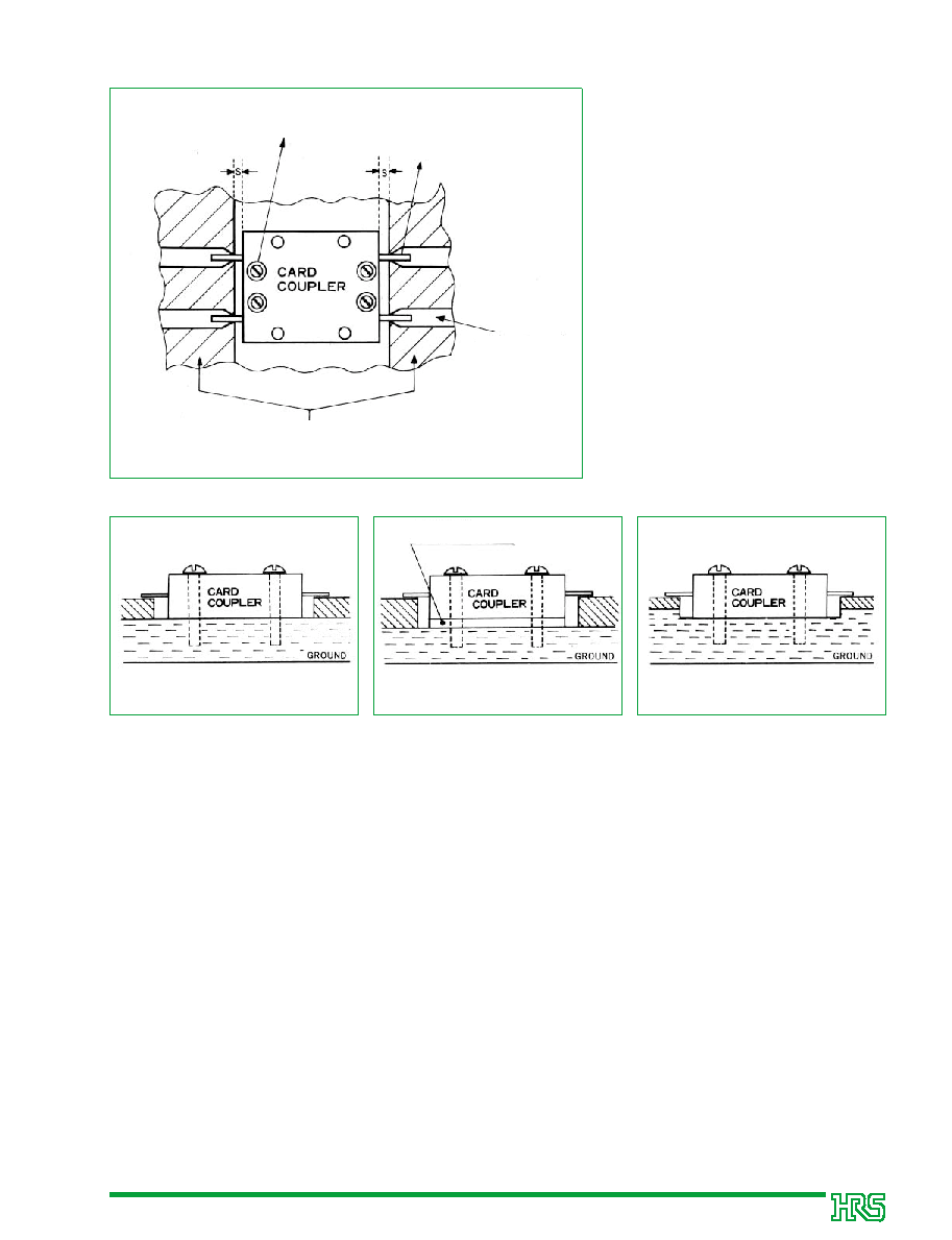
sMounting Method
Directional Card couplers (720 to 1600 MHz)
Figure 1.
Figure 3.
Figure 4.
Fastening screw
Microstrip board
Micro stripline
Tab
Figure 2.
The three types of mounting methods
illustrated in the diagrams below will
mount the card coupler for use under
optimum conditions.
The fastening screws in the diagrams
are M2 screws tightened to 1.5 kg cm.
When the tip of the micro stripline is of
Teflon type material ( r = 2.6), C
chamfering of C1 is performed at t1.6,
and of C0.5 at t1.2.
The side view diagrams of Figure 1 are
illustrated in Figures 2, 3, and 4 below.
Gap S between the card coupler and
the microstrip board surface should be
used to agree with the following
conditions.
Below 500 MHz ........S≤0.5 mm
500 to 2300 MHz......S≤0.25 mm
Above 2300 MHz......S≤0.15 mm
(
Metal plate or conductive spacer
qWhen the Ground Board is Constructed of 0.4 mm Stainless and 0.8 mm Aluminum
(When the Thickness of the Microstrip Board is 1.6 or 1.2 mm)
For t1.6 boards, use with the stainless case of the card coupler facing upward. For t1.2 boards,
use with the aluminum case of the card coupler facing upward. Mount and fix the card coupler
with fastening screws as illustrated in Figure 2. Next, solder the tabs and micro stripline, then
use.
(When the Thickness of the Microstrip Board is Greater than 1.6 mm)
Insert a metal plate or a conductive spacer between the coupler and ground, then mount as
illustrated in Figure 3 so that the surface of the tabs and the position of the microstrip board are
equal. Fix the card coupler with fastening screws as illustrated in Figure 3. Next, solder the tabs
and micro stripline, then use.
(When the Thickness of the Microstrip Board is Less than 1.2 mm)
Cut the ground at the position of the coupler and attach so that the surface of the tabs is in
contact with the micro stripline. Fix the card coupler with fastening screws as illustrated in Figure
4. Next, solder the tabs and micro stripline, then use.
∏
相关PDF资料 |
PDF描述 |
|---|---|
| HD-0900M(13DB) | 800 MHz - 1000 MHz RF/MICROWAVE DIRECTIONAL COUPLER, 0.7 dB INSERTION LOSS-MAX |
| HD-1500M(20DB) | 1400 MHz - 1600 MHz RF/MICROWAVE DIRECTIONAL COUPLER, 0.5 dB INSERTION LOSS-MAX |
| HD-1500M(6DB) | 1400 MHz - 1600 MHz RF/MICROWAVE DIRECTIONAL COUPLER, 0.5 dB INSERTION LOSS-MAX |
| HD-1500M(10DB) | 1400 MHz - 1600 MHz RF/MICROWAVE DIRECTIONAL COUPLER, 0.5 dB INSERTION LOSS-MAX |
| HD-0900M3-CH(40) | 800 MHz - 1000 MHz RF/MICROWAVE 90 DEGREE HYBRID COUPLER |
相关代理商/技术参数 |
参数描述 |
|---|---|
| HD-0900M3-CH | 制造商:HRS 制造商全称:HRS 功能描述:3 dB 90∑ Card Couplers |
| HD-0900M3-CH-1 | 制造商:HRS 制造商全称:HRS 功能描述:3 dB 90∑ Card Couplers |
| HD-0900M3-CH-2 | 制造商:HRS 制造商全称:HRS 功能描述:3 dB 90∑ Card Couplers |
| HD-0900M3-CH-I | 制造商:HRS 制造商全称:HRS 功能描述:3 dB 90∑ Card Couplers |
| HD1 | 制造商:NEC 制造商全称:NEC 功能描述:on-chip resistor NPN silicon epitaxial transistor For mid-speed switching |
发布紧急采购,3分钟左右您将得到回复。