- 您现在的位置:买卖IC网 > PDF目录385378 > HI-1575 (Holt Integrated Circuits) 3.3V Dual Transceivers with Integrated Encoder / Decoders PDF资料下载
参数资料
| 型号: | HI-1575 |
| 厂商: | Holt Integrated Circuits |
| 英文描述: | 3.3V Dual Transceivers with Integrated Encoder / Decoders |
| 中文描述: | 3.3V双收发器集成编码器/解码器 |
| 文件页数: | 3/12页 |
| 文件大小: | 128K |
| 代理商: | HI-1575 |
HI-1575
3
CLK
Decoder A
6
5
3
2
4
30
10
9
31
13-20,
22-29
1
Decoder B
Encoder
S
T
S
S
STRB
R/W
CHA/CHB
SYNC
R
DATABUS
VDD
RCVA
R
S
21
GND
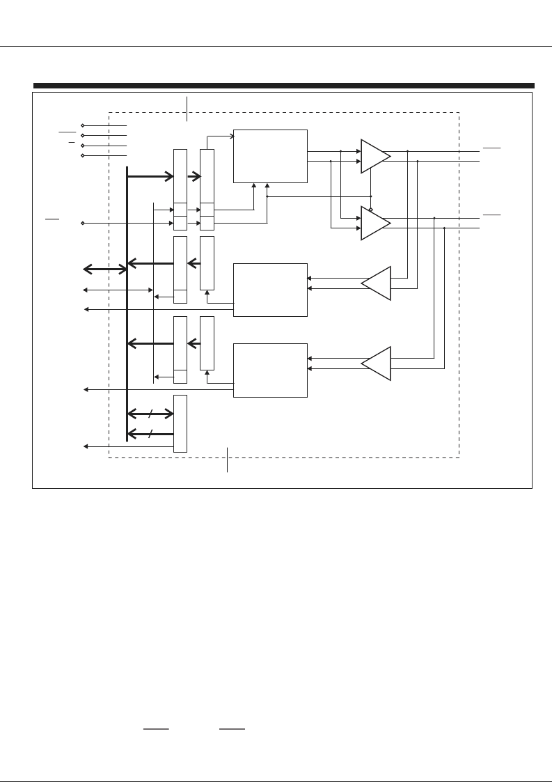
FIGURE 1. HI-1575 BLOCK DIAGRAM
To transmit contiguous words, a second write to the TX
register must occur no earlier than 3.5 us and no later
than 18.5 us after the first TX write. SAM bit 15
(SENDDATA) is high during this period and may be used
as a flag to indicate when the HI-1575 is ready to accept
the next data write for contiguous transmission. When
transmitting a message of three or more words, the third
and subsequent write operations should occur every 20.0
us so as to avoid over-writing the previous data before it is
transferred to the transmitter's shift register.
Figure 3 shows a timing diagram for transmit operations.
The transmitter outputs are either direct or transformer
coupled to the MIL-STD-1553 data bus. Both coupling
methods produce a nominal voltage on the main
MIL-STD-1553 bus of 7.5 volts peak-to-peak, line-to-line.
Figure 6 shows bus coupling examples.
One or both transmitters may be disabled by writing a '1'
into SAM register bits 0 or 1 (TXDISA, TXDISB). When dis-
abled, the host interface works as normal, but there is no
output from the BUSAand
BUSA
(BUSB and
) pins.
BUSB
RECEIVER
The HI-1575's two receivers continuously monitor both
MIL-STD-1553 data busses. Bi-phase differential data
words are accepted from the MIL-STD-1553 bus through
the same direct or transformer coupled interface as the
transmitter. Each receiver’s differential input stage drives
a filter and threshold comparator that presents data to the
decoders.
The decoder logic checks the incoming word for correct
encoding, bit count and parity. If a valid MIL-STD-1553
word is received, the RCVA or RCVB output goes high
and the 16-bit received word is transferred to the RXA or
RXB register. The HI-1575 ERROR output goes high
whenever an encoding error is detected on either bus. If
a received word has an encoding error, then SAM bits 10
or 14 (ERRORA, ERRORB) are set high, and the
corresponding RCVAor RCVB pin is not asserted.
To minimize the number of pins necessary to interface the
HI-1575, the state of RCVA and RCVB can also be read
from SAM bits 7 and 11.
HOLT INTEGRATED CIRCUITS
7
RCVB
11
MR
BUSA
BUSA
BUSB
BUSB
12
ERROR
32
6
10
相关PDF资料 |
PDF描述 |
|---|---|
| HI-1575PCI | 3.3V Dual Transceivers with Integrated Encoder / Decoders |
| HI-1575PCIF | 3.3V Dual Transceivers with Integrated Encoder / Decoders |
| HI-1575PCM | 3.3V Dual Transceivers with Integrated Encoder / Decoders |
| HI-1575PCMF | 3.3V Dual Transceivers with Integrated Encoder / Decoders |
| HI-1575PCT | 3.3V Dual Transceivers with Integrated Encoder / Decoders |
相关代理商/技术参数 |
参数描述 |
|---|---|
| HI-1575_11 | 制造商:HOLTIC 制造商全称:Holt Integrated Circuits 功能描述:MIL-STD-1553 3.3V Dual Transceivers with Integrated Encoder / Decoders |
| HI-1575PCI | 制造商:HOLTIC 制造商全称:Holt Integrated Circuits 功能描述:3.3V Dual Transceivers with Integrated Encoder / Decoders |
| HI-1575PCIF | 制造商:HOLTIC 制造商全称:Holt Integrated Circuits 功能描述:3.3V Dual Transceivers with Integrated Encoder / Decoders |
| HI-1575PCM | 制造商:HOLTIC 制造商全称:Holt Integrated Circuits 功能描述:3.3V Dual Transceivers with Integrated Encoder / Decoders |
| HI-1575PCMF | 制造商:HOLTIC 制造商全称:Holt Integrated Circuits 功能描述:3.3V Dual Transceivers with Integrated Encoder / Decoders |
发布紧急采购,3分钟左右您将得到回复。