参数资料
| 型号: | HI5741BIBZ |
| 厂商: | Intersil |
| 文件页数: | 4/13页 |
| 文件大小: | 0K |
| 描述: | DAC 14BIT 100MHZ 5.2V 28-SOIC |
| 标准包装: | 26 |
| 设置时间: | 20ns |
| 位数: | 14 |
| 数据接口: | 并联 |
| 转换器数目: | 1 |
| 电压电源: | 模拟和数字,双 ± |
| 功率耗散(最大): | 650mW |
| 工作温度: | -40°C ~ 85°C |
| 安装类型: | 表面贴装 |
| 封装/外壳: | 28-SOIC(0.295",7.50mm 宽) |
| 供应商设备封装: | 28-SOIC W |
| 包装: | 管件 |
| 输出数目和类型: | 2 电流,单极;2 电流,双极 |
| 采样率(每秒): | 100M |
12
FN4071.12
September 20, 2006
Signal to Noise Ratio (SNR) is the ratio of a fundamental to
the noise floor of the analog output. The first 5 harmonics
are ignored, and an output filter of 1/2 the clock frequency is
used to eliminate alias products.
Total Harmonic Distortion (THD) is the ratio of the DAC
output fundamental to the RMS sum of the harmonics. The
first 5 harmonics are included, and an output filter of 1/2 the
clock frequency is used to eliminate alias products.
Spurious Free Dynamic Range (SFDR) is the amplitude
difference from a fundamental to the largest harmonically or
non-harmonically related spur. A sine wave is loaded into
the D/A and the output filtered at 1/2 the clock frequency to
eliminate noise from clocking alias terms.
Multi-Tone Power Ratio (MTPR) is the amplitude difference
from peak amplitude to peak distortion (either harmonic or
non-harmonic). An 8 tone pattern is loaded into the D/A. The
tone spacing of this pattern (
f) is created such that tones 1
through 4 and 5 through 8 are spaced equally, with tones 4
and 5 spaced at 2
f. MTPR is measured as the dynamic
range from peak power to peak distortion in the 2
f gap.
Intermodulation Distortion (IMD) is the measure of the
sum and difference products produced when a two tone
input is driven into the D/A. The distortion products created
will arise at sum and difference frequencies of the two tones.
IMD can be calculated using the following equation:
IMD
20Log (RMS of Sum and Difference Distortion Products)
RMS Amplitude of the Fundamental
()
-------------------------------------------------------------------------------------------------------------------------------------------------------
=
ENCODER
CONTROLLER
BASEBAND
BIT
STREAM
K9
C11
B11
33 MSPS
CLK
MOD2
MOD1
HSP45106
SIN15
R4
50
1
2
3
4
5
6
7
8
9
10
15
28
17
18
U2
D13 (MSB)
D12
D11
D10
D9
D8
D7
D6
D5
D4
DVCC
VCC
16
U1
CLK
DGND
HI5741
DVEE
DGND
-5.2V_D
AVEE
AVSS
IOUT
IOUT/
C AMP OUT
C AMP IN
RSET
ARET
REF OUT
21
20
24
25
26
23
19
27
22
R1
64
R2
64
R3
976
C2 0.1F
C1 0.01F
-5.2V_A
FILTER
TO RF
UP-CONVERT
STAGE
L2
10
H
L1
10
H
-5.2V_A
-5.2V_D
C10
MOD0
A11
F10
F9
F11
H11
G11
G9
J11
G10
D10
J10
K11
B8
B6
B7
A7
C7
C6
A6
A5
C5
A4
B4
A3
A2
B3
A1
B10
B9
A10
E11
E9
H10
K2
J2
A8
VCC
PMSEL
ENPOREG
ENOFREG
ENCFREG
ENPHAC
ENTIREG
INHOFR
INITPAC
INITTAC
TEST
PARSER
BINFMT
C15_MSB
C4
C13
C12
C11
C10
C9
C8
C7
C6
C5
C4
C3
C2
C1
C0
A2
A1
A0
CS
WR
PACI
OES
OEC
DACSTRB
SIN14
SIN13
SIN12
SIN11
SIN10
SIN9
SIN8
SIN7
SIN6
SIN5
SIN4
SIN3
SIN2
SIN1
SIN0
L1
K3
L2
L3
L4
J5
K5
L5
K6
J6
J7
L7
L6
L8
K8
L9
L10
COS15
COS14
COS13
COS12
COS11
COS10
COS9
COS8
COS7
COS6
COS5
COS4
COS3
COS2
COS1
COS0
TICO
C2
B1
C1
D1
E3
E2
E1
F2
F3
G3
G1
G2
H1
H2
J1
K1
B2
11
12
D3
D2
-5.2V_A
13
14
D1
D0 (LSB)
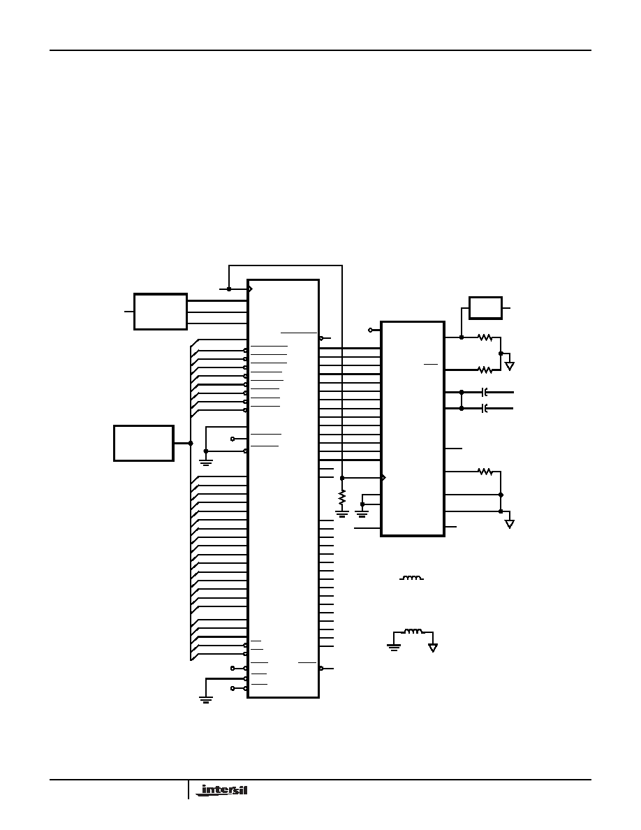
FIGURE 27. PSK MODULATOR USING THE HI5741 AND HSP45106 16-BIT NCO
HI5741
相关PDF资料 |
PDF描述 |
|---|---|
| HI5746KCB-T | CONV A/D 10BIT 40MSPS 28-SOIC |
| HI5760BIBZ | CONV D/A 10-BIT 125MSPS 28-SOIC |
| HI5762/6IN | CONV A/DDUAL 10BIT 60MSPS 44MQFP |
| HI5766KCB | CONV A/D 10BIT 60MSPS 28-SOIC |
| HI5767/6IB | CONV A/D 10BIT 60MSPS 28-SOIC |
相关代理商/技术参数 |
参数描述 |
|---|---|
| HI5741BIBZ-T | 功能描述:数模转换器- DAC HI5741BIB IN TAPE RoHS:否 制造商:Texas Instruments 转换器数量:1 DAC 输出端数量:1 转换速率:2 MSPs 分辨率:16 bit 接口类型:QSPI, SPI, Serial (3-Wire, Microwire) 稳定时间:1 us 最大工作温度:+ 85 C 安装风格:SMD/SMT 封装 / 箱体:SOIC-14 封装:Tube |
| HI5741BIP | 制造商:Rochester Electronics LLC 功能描述:28 PDIP INDTEMP D/A 14 BIT 100 MHZ -5.2V - Bulk 制造商:Harris Corporation 功能描述: 制造商:Intersil Corporation 功能描述: |
| HI5741BIPS2503 | 制造商:Rochester Electronics LLC 功能描述:- Bulk |
| HI5741D DIE | 制造商:Harris Corporation 功能描述: |
| HI5741-EVS | 功能描述:数据转换 IC 开发工具 HI5741 EVAL PL ATFORM RoHS:否 制造商:Texas Instruments 产品:Demonstration Kits 类型:ADC 工具用于评估:ADS130E08 接口类型:SPI 工作电源电压:- 6 V to + 6 V |
发布紧急采购,3分钟左右您将得到回复。