- 您现在的位置:买卖IC网 > PDF目录385381 > HI7106CM44 (INTERSIL CORP) 3 1/2 Digit, LCD/LED Display, A/D Converter PDF资料下载
参数资料
| 型号: | HI7106CM44 |
| 厂商: | INTERSIL CORP |
| 元件分类: | ADC |
| 英文描述: | 3 1/2 Digit, LCD/LED Display, A/D Converter |
| 中文描述: | 1-CH 3-BIT DUAL-SLOPE ADC, PARALLEL ACCESS, PQFP44 |
| 封装: | 10 X 10 MM, METRIC, PLASTIC, MO-108AA-2, QFP-44 |
| 文件页数: | 5/11页 |
| 文件大小: | 123K |
| 代理商: | HI7106CM44 |
5
De-Integrate Phase
The final phase is de-integrate, or reference integrate. Input
low is internally connected to analog COMMON and input
high is connected across the previously charged reference
capacitor. Circuitry within the chip ensures that the capacitor
will be connected with the correct polarity to cause the
integrator output to return to zero. The time required for the
output to return to zero is proportional to the input signal.
Specifically the digital reading displayed is:
.
Differential Input
The input can accept differential voltages anywhere within
the common mode range of the input amplifier, or specifically
from 0.5V below the positive supply to 1V above the
negative supply. In this range, the system has a CMRR of
86dB typical. However, care must be exercised to assure the
integrator output does not saturate. A worst case condition
would be a large positive common mode voltage with a near
full scale negative differential input voltage. The negative
input signal drives the integrator positive when most of its
swing has been used up by the positive common mode
voltage. For these critical applications the integrator output
swing can be reduced to less than the recommended 2V full
scale swing with little loss of accuracy. The integrator output
can swing to within 0.3V of either supply without loss of
linearity.
Differential Reference
The reference voltage can be generated anywhere within the
power supply voltage of the converter. The main source of
common mode error is a roll-over voltage caused by the
reference capacitor losing or gaining charge to stray capacity
on its nodes. If there is a large common mode voltage, the
reference capacitor can gain charge (increase voltage) when
called up to de-integrate a positive signal but lose charge
(decrease voltage) when called up to de-integrate a negative
input signal. This difference in reference for positive or
negative input voltage will give a roll-over error. However, by
selecting the reference capacitor such that it is large enough
in comparison to the stray capacitance, this error can be
held to less than 0.5 count worst case. (See Component
Value Selection.)
Analog COMMON
This pin is included primarily to set the common mode voltage
for battery operation or for any system where the input signals
are floating with respect to the power supply. The COMMON
pin sets a voltage that is approximately 2.8V more negative
than the positive supply. This is selected to give a minimum
end-of-life battery voltage of about 6V. However, analog COM-
MON has some of the attributes of a reference voltage. When
the total supply voltage is large enough to cause the zener to
regulate (>7V), the COMMON voltage will have a low voltage
coefficient (0.001%/V), low output impedance (
15
), and a
temperature coefficient typically less than 80ppm/
o
C. An exter-
nal reference can easily be added, as shown in Figure 3.
Analog COMMON is also used as the input low return during
auto-zero and de-integrate. If IN LO is different from analog
COMMON, a common mode voltage exists in the system
and is taken care of by the excellent CMRR of the converter.
However, in some applications IN LO will be set at a fixed
known voltage (power supply common for instance). In this
application, analog COMMON should be tied to the same
point, thus removing the common mode voltage from the
converter. The same holds true for the reference voltage. If
reference can be conveniently tied to analog COMMON, it
should be since this removes the common mode voltage
from the reference system.
Within the lC, analog COMMON is tied to an N-Channel FET
that can sink approximately 30mA of current to hold the
voltage 2.8V below the positive supply (when a load is trying
to pull the common line positive). However, there is only
10
μ
A of source current, so COMMON may easily be tied to a
more negative voltage thus overriding the internal reference.
TEST
The TEST pin serves two functions. On the HI7106 it is cou-
pled to the internally generated digital supply through a
500
resistor. Thus it can be used as the negative supply for
externally generated segment drivers such as decimal points
or any other presentation the user may want to include on
the LCD display. Figures 4 and 5 show such an application.
No more than a 1mA load should be applied.
DISPLAY COUNT = 1000
V
REF
--------------
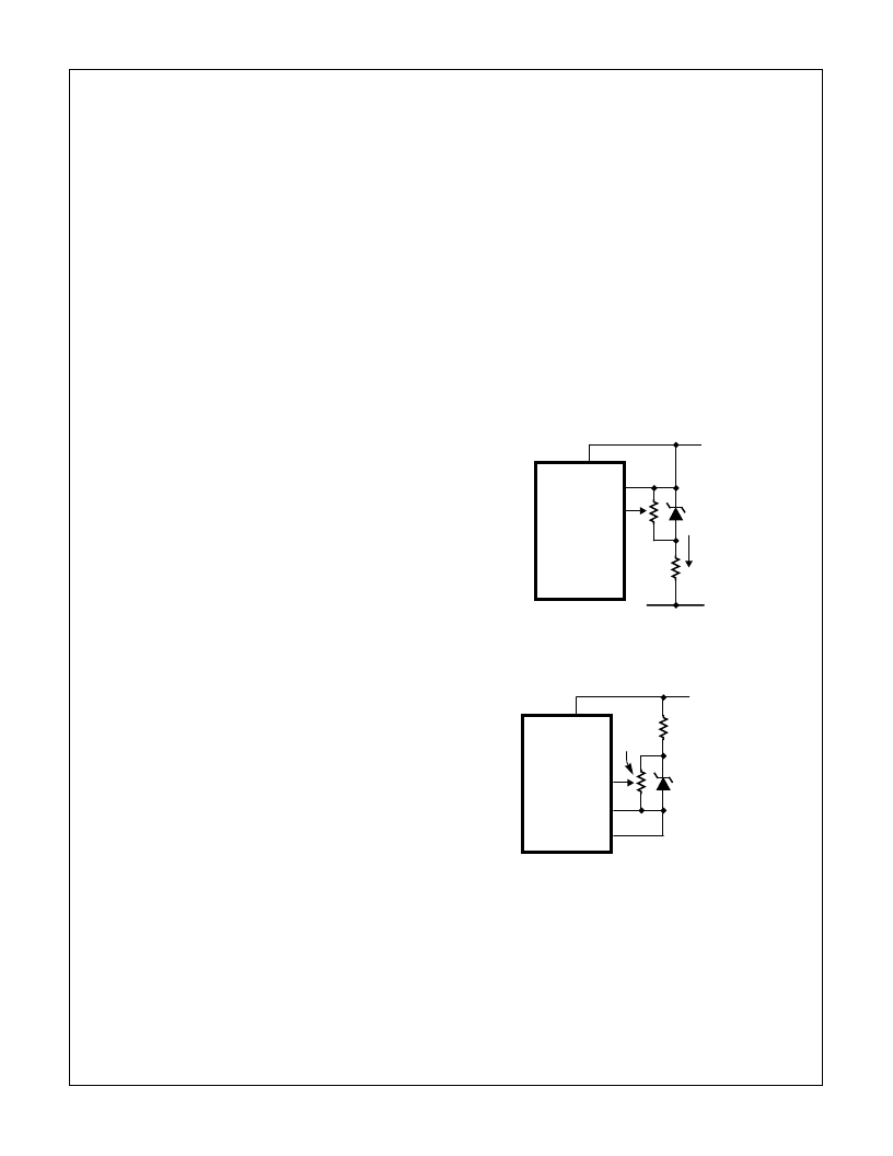
FIGURE 3A.
FIGURE 3B.
FIGURE 3. USING AN EXTERNAL REFERENCE
HI7106
V
REF LO
REF HI
V+
V-
6.8V
ZENER
I
Z
HI7106
V
REF HI
REF LO
COMMON
V+
ICL8069
1.2V
REFERENCE
6.8k
20k
HI7106
相关PDF资料 |
PDF描述 |
|---|---|
| HI7106CPL | 3 1/2 Digit, LCD/LED Display, A/D Converter |
| HI7106D | 3 1/2 Digit, LCD/LED Display, A/D Converter |
| HI7131 | 3 1/2 Digit, Low Power, High CMRR, LCD/LED Display-Type A/D Converters |
| HI7131CM44 | 3 1/2 Digit, Low Power, High CMRR, LCD/LED Display-Type A/D Converters |
| HI7131CPL | 3 1/2 Digit, Low Power, High CMRR, LCD/LED Display-Type A/D Converters |
相关代理商/技术参数 |
参数描述 |
|---|---|
| HI7106CPL | 制造商:Rochester Electronics LLC 功能描述:- Bulk |
| HI7106D | 制造商:INTERSIL 制造商全称:Intersil Corporation 功能描述:3 1/2 Digit, LCD/LED Display, A/D Converter |
| HI7131 | 制造商:INTERSIL 制造商全称:Intersil Corporation 功能描述:3 1/2 Digit, Low Power, High CMRR, LCD/LED Display-Type A/D Converters |
| HI7131_02 | 制造商:INTERSIL 制造商全称:Intersil Corporation 功能描述:3 1/2 Digit, Low Power, High CMRR, LCD/LED Display-Type A/D Converters |
| HI7131CM44 | 制造商:Rochester Electronics LLC 功能描述:- Bulk 制造商:Harris Corporation 功能描述: |
发布紧急采购,3分钟左右您将得到回复。