- 您现在的位置:买卖IC网 > PDF目录385381 > HI7133 (Intersil Corporation) 3 1/2 Digit, Low Power, High CMRR, LCD/LED Display-Type A/D Converters PDF资料下载
参数资料
| 型号: | HI7133 |
| 厂商: | Intersil Corporation |
| 元件分类: | 串行ADC |
| 英文描述: | 3 1/2 Digit, Low Power, High CMRR, LCD/LED Display-Type A/D Converters |
| 中文描述: | 3 1 / 2位,低功耗,高CMRR,液晶/ LED显示型的A / D转换器 |
| 文件页数: | 14/21页 |
| 文件大小: | 209K |
| 代理商: | HI7133 |
3-1839
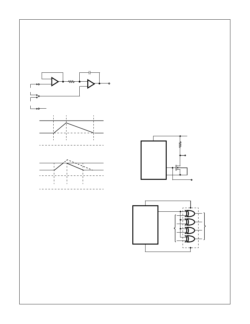
A worst case condition would be a large positive common-
mode voltage with a near full scale negative differential input
voltage. The negative input signal drives the integrator posi-
tive when most of its swing has been used up by the positive
common mode voltage. For these critical applications the
integrator output swing can be reduced to less than the rec-
ommended 2V full scale swing with little loss of accuracy.
The integrator output can swing to within 0.3V of either
supply without loss of linearity.
Differential Reference (REF HI, REF LO) and Reference
Capacitor Pins (C
REF
+, C
REF
-)
As was discussed in the analog section (Figure 5), the differ-
ential reference pins are connected across the reference
capacitor (connected to pins C
REF
+ and C
REF
-) to charge it
during the zero integrate and the auto-zero phase. Then the
reference capacitor is used as either a positive or negative
reference during the deintegrate phase. The reference
capacitor acts as a flying capacitor between the reference
voltage and integrator inputs in the deintegrate phase.
The common mode voltage range for the reference inputs is
V+ to V-. The reference voltage can be generated anywhere
within the power supply range of the converter. The main
source of rollover error is reference common mode voltage
caused by the reference capacitor losing or gaining charge
to or from stray capacitance on its nodes. If there is a large
common mode voltage, the reference capacitor can gain
charge (increase voltage) when called upon to deintegrate a
positive signal but lose charge (decrease voltage) when
called up to deintegrate a negative input signal. This change
in reference for positive or negative input voltage will give a
rollover error. However, by selecting the reference capacitor
such that it is large enough in comparison to the stray capac-
itances, this error can be held to less than 0.5 counts worst
case. See the “Component Value Selection” section for
auto-zero capacitor value.
TEST Pin
The TEST pin serves two functions. It is coupled to the
internally generated digital ground through an effective 500
resistor. Thus, it can be used as the digital ground for external
digital circuits such as segment drivers for decimal points or
any other annunciator the user may want to include on the
LCD display. For these applications the external digital circuit
should be supplied between V+ and TEST pin. Figures 9 and
10 show such an application. In Figure 9 a MOSFET transis-
tor is used to invert the BP signal to drive the decimal point.
The MOSFET can be any general purpose type with a thresh-
old voltage less than 3.5V and ON resistance less than 500
.
Figure 10 uses an CMOS IC XOR gate to generate controlla-
ble decimal point drives. No more than a 1mA load should be
applied to TEST pin by any external digital circuitry.
The second function of the TEST pin is the “lamp test”.
When the TEST pin is pulled high (to V+) all segments will
be turned on and the display should read -1888. The test pin
will sink about 10mA under these conditions.
CAUTION: In the lamp test mode, the segments have a constant DC
voltage (no square-wave). This may burn the LCD display if
maintained for extended periods.
-
+
-
+
C
INT
R
INT
V
INT
IN HI
V
IN
IN LO
V
CM
(COMMON MODE VOLTAGE)
(V+ - V-)/2
INTEGRATOR OUTPUT WITH IN LO TOO
CLOSE TO POSITIVE SUPPLY RAIL (NEGATIVE INPUT)
V+
IN LO
V-
AZ
INT.
DEINT.
NORMAL INTEGRATOR OUTPUT
WAVEFORM (NEGATIVE INPUT)
V+
IN LO
V-
AZ
INT.
DEINT.
FIGURE 96. COMMON MODE VOLTAGE CONSIDERATION
HI7131/33
V+
BP
TEST
21
37
TO LCD
BACKPLANE
TO LCD
DECIMAL
POINT
1M
FIGURE 97. SIMPLE INVERTER FOR FIXED DECIMAL POINT
DRIVE
HI7131/33
V+
BP
TEST
DECIMAL
POINT
SELECT
CD4070B
GND
V+
TO LCD
DECIMAL
POINTS
FIGURE 98. EXCLUSIVE “OR” GATE FOR DECIMAL POINTS
AND ANNUNCIATORS DRIVE
HI7131, HI7133
相关PDF资料 |
PDF描述 |
|---|---|
| HI7133CM44 | 3 1/2 Digit, Low Power, High CMRR, LCD/LED Display-Type A/D Converters |
| HI7133CPL | Power Resistor; Series:200; Resistance:4.5kohm; Resistance Tolerance: 5%; Power Rating:8W; Resistor Element Material:Ceramic; Temperature Coefficient:260 ppm; Leaded Process Compatible:No; Packaging:Bulk RoHS Compliant: No |
| HI7190IP | null24-Bit, High Precision, Sigma Delta A/D Converter |
| HI7190EVAL | null24-Bit, High Precision, Sigma Delta A/D Converter |
| HI7190IB | null24-Bit, High Precision, Sigma Delta A/D Converter |
相关代理商/技术参数 |
参数描述 |
|---|---|
| HI7133 WAF | 制造商:Harris Corporation 功能描述: |
| HI7133CM44 | 制造商:Rochester Electronics LLC 功能描述:- Bulk |
| HI7133CM44S2324 | 制造商:Rochester Electronics LLC 功能描述:- Bulk |
| HI7133CPL | 制造商:Rochester Electronics LLC 功能描述:- Bulk 制造商:Harris Corporation 功能描述: |
| HI7151 | 制造商:未知厂家 制造商全称:未知厂家 功能描述:Converter IC |
发布紧急采购,3分钟左右您将得到回复。