- 您现在的位置:买卖IC网 > PDF目录385382 > HIP6004BCB (INTERSIL CORP) Buck and Synchronous-Rectifier (PWM) Controller and Output Voltage Monitor PDF资料下载
参数资料
| 型号: | HIP6004BCB |
| 厂商: | INTERSIL CORP |
| 元件分类: | 稳压器 |
| 英文描述: | Buck and Synchronous-Rectifier (PWM) Controller and Output Voltage Monitor |
| 中文描述: | SWITCHING CONTROLLER, 215 kHz SWITCHING FREQ-MAX, PDSO20 |
| 封装: | PLASTIC, MS-013AC, SOIC-20 |
| 文件页数: | 6/12页 |
| 文件大小: | 339K |
| 代理商: | HIP6004BCB |
Functional Description
Initialization
The HIP6004B automatically initializes upon receipt of power.
Special sequencing of the input supplies is not necessary. The
Power-On Reset (POR) function continually monitors the input
supply voltages. The POR monitors the bias voltage at the V
CC
pin and the input voltage (V
IN
) on the OCSET pin. The level on
OCSET is equal to V
IN
less a fixed voltage drop (see over-
current protection). The POR function initiates soft start
operation after both input supply voltages exceed their POR
thresholds. For operation with a single +12V power source, V
IN
and V
CC
are equivalent and the +12V power source must
exceed the rising V
CC
threshold before POR initiates operation.
Soft Start
The POR function initiates the soft start sequence. An internal
10
μ
A current source charges an external capacitor (C
SS
) on
the SS pin to 4V. Soft start clamps the error amplifier output
(COMP pin) and reference input (+ terminal of error amp) to the
SS pin voltage. Figure 3 shows the soft start interval with
C
SS
= 0.1
μ
F. Initially the clamp on the error amplifier (COMP
pin) controls the converter’s output voltage. At t
1
in Figure 3,
the SS voltage reaches the valley of the oscillator’s triangle
wave. The oscillator’s triangular waveform is compared to the
ramping error amplifier voltage. This generates PHASE pulses
of increasing width that charge the output capacitor(s). This
interval of increasing pulse width continues to t
2
. With sufficient
output voltage, the clamp on the reference input controls the
output voltage. This is the interval between t
2
and t
3
in Figure 3.
At t
3
the SS voltage exceeds the DACOUT voltage and the
output voltage is in regulation. This method provides a rapid
and controlled output voltage rise. The PGOOD signal toggles
‘high’ when the output voltage (V
SEN
pin) is within
±
5% of
DACOUT. The 2% hysteresis built into the power good
comparators prevents PGOOD oscillation due to nominal
output voltage ripple.
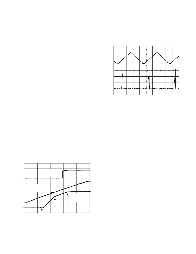
Over-Current Protection
The over-current function protects the converter from a
shorted output by using the upper MOSFET’s on-resistance,
r
DS(ON)
to monitor the current. This method enhances the
converter’s efficiency and reduces cost by eliminating a
current sensing resistor.
The over-current function cycles the soft-start function in a
hiccup mode to provide fault protection. A resistor (R
OCSET
)
programs the over-current trip level. An internal 200
μ
A current
sink develops a voltage across R
OCSET
that is referenced to
V
IN
. When the voltage across the upper MOSFET (also
referenced to V
IN
) exceeds the voltage across R
OCSET
, the
over-current function initiates a soft-start sequence. The soft-
start function discharges C
SS
with a 10
μ
A current sink and
inhibits PWM operation. The soft-start function recharges
C
SS
, and PWM operation resumes with the error amplifier
clamped to the SS voltage. Should an overload occur while
recharging C
SS
, the soft start function inhibits PWM operation
while fully charging C
SS
to 4V to complete its cycle. Figure 4
shows this operation with an overload condition. Note that the
inductor current increases to over 15A during the C
SS
charging interval and causes an over-current trip. The
converter dissipates very little power with this method. The
measured input power for the conditions of Figure 4 is 2.5W.
The over-current function will trip at a peak inductor current
(I
PEAK)
determined by:
I
x R
DS ON
)
where I
OCSET
is the internal OCSET current source
(200
μ
A typical). The OC trip point varies mainly due to the
MOSFET’s r
DS(ON)
variations. To avoid over-current
tripping in the normal operating load range, find the
R
OCSET
resistor from the equation above with:
1. The maximum r
DS(ON)
at the highest junction temperature.
2. The minimum I
OCSET
from the specification table.
3. Determine I
PEAK
for
where
I is the output inductor ripple current.
,
0V
0V
0V
TIME (5ms/DIV.)
SOFT-START
(1V/DIV.)
OUTPUT
VOLTAGE
(1V/DIV.)
t
2
t
3
PGOOD
(2V/DIV.)
t
1
FIGURE 3. SOFT START INTERVAL
O
S
0A
0V
TIME (20ms/DIV.)
5A
10A
15A
2V
4V
FIGURE 4. OVER-CURRENT OPERATION
I
PEAK
----------------------------------------------------
=
I
PEAK
I
OUT MAX
(
)
I
(
)
2
+
>
HIP6004B
相关PDF资料 |
PDF描述 |
|---|---|
| HIP6004BCV | Buck and Synchronous-Rectifier (PWM) Controller and Output Voltage Monitor |
| HIP6004ECBZ | Buck and Synchronous-Rectifier (PWM) Controller and Output Voltage Monitor |
| HIP6004ECVZ | Buck and Synchronous-Rectifier (PWM) Controller and Output Voltage Monitor |
| HIP6004E | Buck and Synchronous-Rectifier (PWM) Controller and Output Voltage Monitor |
| HIP6004ECB | Buck and Synchronous-Rectifier (PWM) Controller and Output Voltage Monitor |
相关代理商/技术参数 |
参数描述 |
|---|---|
| HIP6004BCB-T | 功能描述:IC CTRLR PWM VOLTAGE MON 20-SOIC RoHS:否 类别:集成电路 (IC) >> PMIC - 稳压器 - 专用型 系列:- 产品培训模块:Lead (SnPb) Finish for COTS Obsolescence Mitigation Program 标准包装:2,000 系列:- 应用:电源,ICERA E400,E450 输入电压:4.1 V ~ 5.5 V 输出数:10 输出电压:可编程 工作温度:-40°C ~ 85°C 安装类型:表面贴装 封装/外壳:42-WFBGA,WLCSP 供应商设备封装:42-WLP 包装:带卷 (TR) |
| HIP6004BCBZ | 功能描述:电压模式 PWM 控制器 PWM CNTRLR 3 5 TO 1 3 DAC RNG 20LD RoHS:否 制造商:Texas Instruments 输出端数量:1 拓扑结构:Buck 输出电压:34 V 输出电流: 开关频率: 工作电源电压:4.5 V to 5.5 V 电源电流:600 uA 最大工作温度:+ 125 C 最小工作温度:- 40 C 封装 / 箱体:WSON-8 封装:Reel |
| HIP6004BCBZA | 功能描述:电压模式 PWM 控制器 W/ANNEAL PWM CNTRLR 3 5 TO 1 3 DAC RNG RoHS:否 制造商:Texas Instruments 输出端数量:1 拓扑结构:Buck 输出电压:34 V 输出电流: 开关频率: 工作电源电压:4.5 V to 5.5 V 电源电流:600 uA 最大工作温度:+ 125 C 最小工作温度:- 40 C 封装 / 箱体:WSON-8 封装:Reel |
| HIP6004BCBZA-T | 功能描述:电压模式 PWM 控制器 W/ANNEAL PWM CNTRLR 3 5V TO 1 3V DAC RoHS:否 制造商:Texas Instruments 输出端数量:1 拓扑结构:Buck 输出电压:34 V 输出电流: 开关频率: 工作电源电压:4.5 V to 5.5 V 电源电流:600 uA 最大工作温度:+ 125 C 最小工作温度:- 40 C 封装 / 箱体:WSON-8 封装:Reel |
| HIP6004BCBZ-T | 功能描述:电压模式 PWM 控制器 PWM CNTRLR 3 5V TO 1 3V DAC 20LD TA RoHS:否 制造商:Texas Instruments 输出端数量:1 拓扑结构:Buck 输出电压:34 V 输出电流: 开关频率: 工作电源电压:4.5 V to 5.5 V 电源电流:600 uA 最大工作温度:+ 125 C 最小工作温度:- 40 C 封装 / 箱体:WSON-8 封装:Reel |
发布紧急采购,3分钟左右您将得到回复。