- 您现在的位置:买卖IC网 > PDF目录371821 > HIP6303CB (INTERSIL CORP) Microprocessor CORE Voltage Regulator Multi-Phase Buck PWM Controller PDF资料下载
参数资料
| 型号: | HIP6303CB |
| 厂商: | INTERSIL CORP |
| 元件分类: | 稳压器 |
| 英文描述: | Microprocessor CORE Voltage Regulator Multi-Phase Buck PWM Controller |
| 中文描述: | SWITCHING CONTROLLER, 1500 kHz SWITCHING FREQ-MAX, PDSO20 |
| 封装: | PLASTIC, MS-013AC, SOIC-20 |
| 文件页数: | 15/17页 |
| 文件大小: | 195K |
| 代理商: | HIP6303CB |
15
Output Inductor Selection
One of the parameters limiting the converter’s response to a
load transient is the time required to change the inductor
current. Small inductors in a multi-phase converter reduces
the response time without significant increases in total ripple
current.
The output inductor of each power channel controls the
ripple current. The control IC is stable for channel ripple
current (peak-to-peak) up to twice the average current. A
single channel’s ripple current is approximately:
The current from multiple channels tend to cancel each other
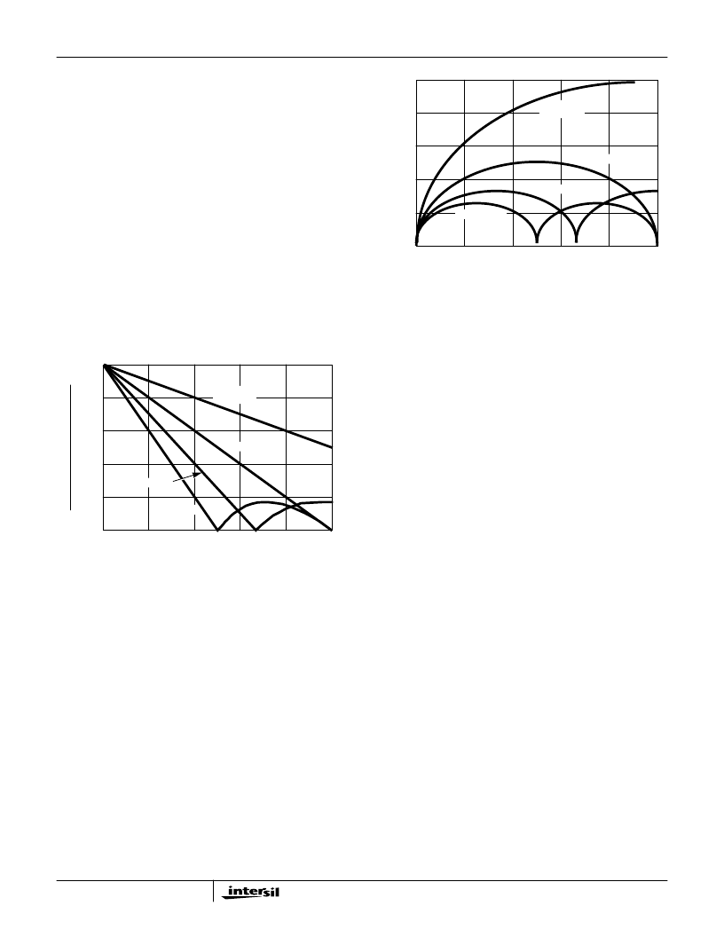
and reduce the total ripple current. Figure 12 gives the total
ripple current as a function of duty cycle, normalized to the
parameter
at zero duty cycle. To determine
the total ripple current from the number of channels and the
duty cycle, multiply the y-axis value by
.
Small values of output inductance can cause excessive power
dissipation. The HIP6303 is designed for stable operation for
ripple currents up to twice the load current. However, for this
condition, the RMS current is 115% above the value shown in
the following MOSFET Selection and Considerations section.
With all else fixed, decreasing the inductance could increase
the power dissipated in the MOSFETs by 30%.
Input Capacitor Selection
The important parameters for the bulk input capacitors are
the voltage rating and the RMS current rating. For reliable
operation, select bulk input capacitors with voltage and
current ratings above the maximum input voltage and largest
RMS current required by the circuit. The capacitor voltage
rating should be at least 1.25 times greater than the
maximum input voltage and a voltage rating of 1.5 times is a
conservative guideline. The RMS current required for a
multi-phase converter can be approximated with the aid of
Figure 13.
First determine the operating duty ratio as the ratio of the
output voltage divided by the input voltage. Find the Current
Multiplier from the curve with the appropriate power
channels. Multiply the current multiplier by the full load
output current. The resulting value is the RMS current rating
required by the input capacitor.
Use a mix of input bypass capacitors to control the voltage
overshoot across the MOSFETs. Use ceramic capacitance
for the high frequency decoupling and bulk capacitors to
supply the RMS current. Small ceramic capacitors should be
placed very close to the drain of the upper MOSFET to
suppress the voltage induced in the parasitic circuit
impedances.
For bulk capacitance, several electrolytic capacitors
(Panasonic HFQ series or Nichicon PL series or Sanyo
MV-GX or equivalent) may be needed. For surface mount
designs, solid tantalum capacitors can be used, but caution
must be exercised with regard to the capacitor surge current
rating. These capacitors must be capable of handling the
surge-current at power-up. The TPS series available from
AVX, and the 593D series from Sprague are both surge
current tested.
MOSFET Selection and Considerations
In high-current PWM applications, the MOSFET power
dissipation, package selection and heatsink are the
dominant design factors. The power dissipation includes two
loss components; conduction loss and switching loss. These
losses are distributed between the upper and lower
MOSFETs according to duty factor (see the following
equations). The conduction losses are the main component
of power dissipation for the lower MOSFETs, Q2 and Q4 of
Figure 1. Only the upper MOSFETs, Q1 and Q3 have
significant switching losses, since the lower device turns on
and off into near zero voltage.
The equations assume linear voltage-current transitions and
do not model power loss due to the reverse-recovery of the
lower MOSFETs body diode. The gate-charge losses are
I
V
SW
V
–
-------------------------------
V
IN
---------------
×
=
Vo
(
)
LxF
SW
(
)
Vo
(
)
LxF
SW
(
)
1.0
0.8
0.6
0.4
0.2
0
0
0.1
0.2
0.3
0.4
0.5
DUTY CYCLE (V
O
/V
IN
)
R
P
)
V
O
/
X
S
)
SINGLE
CHANNEL
2 CHANNEL
3 CHANNEL
4 CHANNEL
FIGURE 12. RIPPLE CURRENT vs DUTY CYCLE
0.5
0.4
0.3
0.2
0.1
0
0
0.1
0.2
0.3
0.4
0.5
DUTY CYCLE (V
O
/V
IN
)
C
SINGLE
CHANNEL
3 CHANNEL
4 CHANNEL
2 CHANNEL
FIGURE 13. CURRENT MULTIPLIER vs DUTY CYCLE
HIP6303
相关PDF资料 |
PDF描述 |
|---|---|
| HIP6303EVAL1 | Microprocessor CORE Voltage Regulator Multi-Phase Buck PWM Controller |
| HIP6304CB-T | Microprocessor CORE Voltage Regulator Multi-Phase Buck PWM Controller |
| HIP6304 | Microprocessor CORE Voltage Regulator Multi-Phase Buck PWM Controller(微处理器核心电压稳压器多相PWM控制电路) |
| HIP6304CB | 150000 SYSTEM GATE 2.5 VOLT FPGA - NOT RECOMMENDED for NEW DESIGN |
| HIP6304EVAL1 | Microprocessor CORE Voltage Regulator Multi-Phase Buck PWM Controller |
相关代理商/技术参数 |
参数描述 |
|---|---|
| HIP6303CB WAF | 制造商:Harris Corporation 功能描述: |
| HIP6303CB-T | 功能描述:IC REG CTRLR BUCK PWM 20-SOIC RoHS:否 类别:集成电路 (IC) >> PMIC - 稳压器 - DC DC 切换控制器 系列:- 标准包装:4,000 系列:- PWM 型:电压模式 输出数:1 频率 - 最大:1.5MHz 占空比:66.7% 电源电压:4.75 V ~ 5.25 V 降压:是 升压:无 回扫:无 反相:无 倍增器:无 除法器:无 Cuk:无 隔离:无 工作温度:-40°C ~ 85°C 封装/外壳:40-VFQFN 裸露焊盘 包装:带卷 (TR) |
| HIP6303EVAL1 | 制造商:INTERSIL 制造商全称:Intersil Corporation 功能描述:Microprocessor CORE Voltage Regulator Multi-Phase Buck PWM Controller |
| HIP6304 | 制造商:INTERSIL 制造商全称:Intersil Corporation 功能描述:Microprocessor CORE Voltage Regulator Multi-Phase Buck PWM Controller |
| HIP6304 WAF | 制造商:Intersil Corporation 功能描述: |
发布紧急采购,3分钟左右您将得到回复。