- 您现在的位置:买卖IC网 > PDF目录371821 > HIP6304 (Intersil Corporation) Microprocessor CORE Voltage Regulator Multi-Phase Buck PWM Controller(微处理器核心电压稳压器多相PWM控制电路) PDF资料下载
参数资料
| 型号: | HIP6304 |
| 厂商: | Intersil Corporation |
| 英文描述: | Microprocessor CORE Voltage Regulator Multi-Phase Buck PWM Controller(微处理器核心电压稳压器多相PWM控制电路) |
| 中文描述: | 微处理器核心电压调节器的多相降压PWM控制器(微处理器核心电压稳压器多相脉宽调制控制电路) |
| 文件页数: | 10/14页 |
| 文件大小: | 176K |
| 代理商: | HIP6304 |
10
R
IN
should be selected to give the desired “droop” voltage at
the normal full load current 50
μ
A applied through the R
ISEN
resistor (or at a different full load current if adjusted as under
“Over-Current, Selecting R
ISEN
” above).
R
IN
= Vdroop / 50
μ
A
For a Vdroop of 80mV, R
IN
= 1.6k
The AC feedback components, R
FB
and Cc, are scaled in
relation to R
IN
.
Current Balancing
The detected currents are also used to balance the phase
currents.
Each phase’s current is compared to the average of the two
phase currents, and the difference is used to create an offset
in that phase’s PWM comparator. The offset is in a direction
to reduce the imbalance.
The balancing circuit can not make up for a difference in
r
DS(ON)
between synchronous rectifiers. If a FET has a higher
r
DS(ON)
, the current through that phase will be reduced.
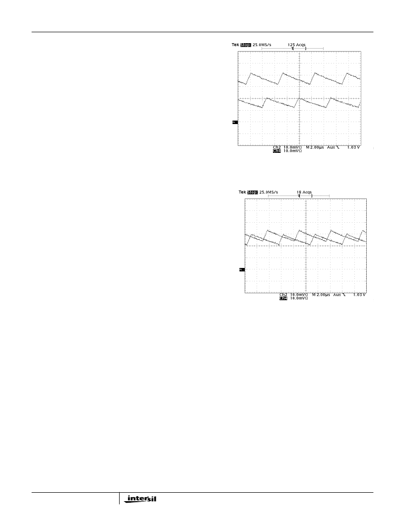
Figures 8 and 9 show the inductor current of a two phase
system without and with current balancing.
Inductor Current
The inductor current in each phase of a multi-phase Buck
converter has two components. There is a current equal to
the load current divided by the number of phases (I
LT
/ n),
and a sawtooth current, (i
PK-PK
) resulting from switching.
The sawtooth component is dependent on the size of the
inductors, the switching frequency of each phase, and the
values of the input and output voltage. Ignoring secondary
effects, such as series resistance, the peak to peak value of
the sawtooth current can be described by:
i
PK-PK
= (V
IN
x V
CORE
- V
CORE2
) / (L x F
SW
x V
IN
)
Where: V
CORE
= DC value of the output or V
ID
voltage
V
IN
= DC value of the input or supply voltage
L = value of the inductor
F
SW
= switching frequency
Example: For V
CORE
=1.6V,
V
IN
=12V,
L =1.3
μ
H,
F
SW
= 250kHz,
Then i
PK-PK
= 4.3A
The inductor, or load current, flows alternately from V
IN
through Q1 and from ground through Q2. The HIP6304
samples the on-state voltage drop across each Q2 transistor
to indicate the inductor current in that phase. The voltage
drop is sampled 1/3 of a switching period, 1/F
SW
, after Q1 is
turned OFF and Q2 is turned on. Because of the sawtooth
current component, the sampled current is different from the
average current per phase. Neglecting secondary effects,
the sampled current (I
SAMPLE
) can be related to the load
current (I
LT
) by:
I
SAMPLE
=
I
LT
/ n +
(V
IN
V
CORE
- 3V
CORE2
) / (6L x F
SW
x V
IN
)
Where: I
LT
= total load current
n = the number of channels
0
5
10
15
20
25
A
FIGURE 8. TWO CHANNEL MULTIPHASE SYSTEM WITH
CURRENT BALANCING DISABLED
0
5
10
15
20
25
A
FIGURE 9. TWO CHANNEL MULTIPHASE SYSTEM WITH
CURRENT BALANCING ENABLED
HIP6304
相关PDF资料 |
PDF描述 |
|---|---|
| HIP6304CB | 150000 SYSTEM GATE 2.5 VOLT FPGA - NOT RECOMMENDED for NEW DESIGN |
| HIP6304EVAL1 | Microprocessor CORE Voltage Regulator Multi-Phase Buck PWM Controller |
| HIP6500B | Multiple Linear Power Controller with ACPI Control Interface |
| HIP6500BCB | Multiple Linear Power Controller with ACPI Control Interface |
| HIP6500BEVAL1 | Multiple Linear Power Controller with ACPI Control Interface |
相关代理商/技术参数 |
参数描述 |
|---|---|
| HIP6304 WAF | 制造商:Intersil Corporation 功能描述: |
| HIP6304CB | 制造商:Rochester Electronics LLC 功能描述:- Bulk 制造商:Intersil Corporation 功能描述: |
| HIP6304CB-T | 制造商:Rochester Electronics LLC 功能描述:- Tape and Reel 制造商:Intersil Corporation 功能描述: |
| HIP6304EVAL1 | 制造商:INTERSIL 制造商全称:Intersil Corporation 功能描述:Microprocessor CORE Voltage Regulator Multi-Phase Buck PWM Controller |
| HIP6311 | 制造商:INTERSIL 制造商全称:Intersil Corporation 功能描述:Microprocessor CORE Voltage Regulator Multi-Phase Buck PWM Controller |
发布紧急采购,3分钟左右您将得到回复。