- 您现在的位置:买卖IC网 > PDF目录385382 > HIP6502 (Intersil Corporation) Multiple Linear Power Controller with ACPI Control Interface PDF资料下载
参数资料
| 型号: | HIP6502 |
| 厂商: | Intersil Corporation |
| 元件分类: | 基准电压源/电流源 |
| 英文描述: | Multiple Linear Power Controller with ACPI Control Interface |
| 中文描述: | 多重线性电源控制器ACPI控制接口 |
| 文件页数: | 9/14页 |
| 文件大小: | 147K |
| 代理商: | HIP6502 |
9
SOFT-START INTO ACTIVE STATES (S0, S1)
If both S3 and S5 are logic high at the time the 5VSB is
applied, the HIP6502 will assume active state wake-up and
keep off the controlled external transistors and the VCLK
output until some time (typically 25ms) after the ATX’s main
outputs used by the application (3.3V, 5V, and 12V) exceed
the set thresholds. This time-out feature is necessary in
order to insure the main ATX outputs are stabilized. The
time-out also assures smooth transitions from sleep into
active when sleep states are being supported.
3.3V
DUAL
/3.3V
SB
output, whose operation is only
dependent on 5VSB presence, will come up right as bias
voltage reaches POR level.
During sleep to active state transitions from conditions
where the outputs are initially 0V (such as S5 to S0 transition
on the 5V
DUAL
output with EN5VDL = 0, or simple power-up
sequence directly into active state), the 3.3V
MEM
and
5V
DUAL
outputs go through a quasi soft-start by being pulled
high through the body diodes of the N-Channel MOSFETs
connected between these outputs and the 3.3V and 5V ATX
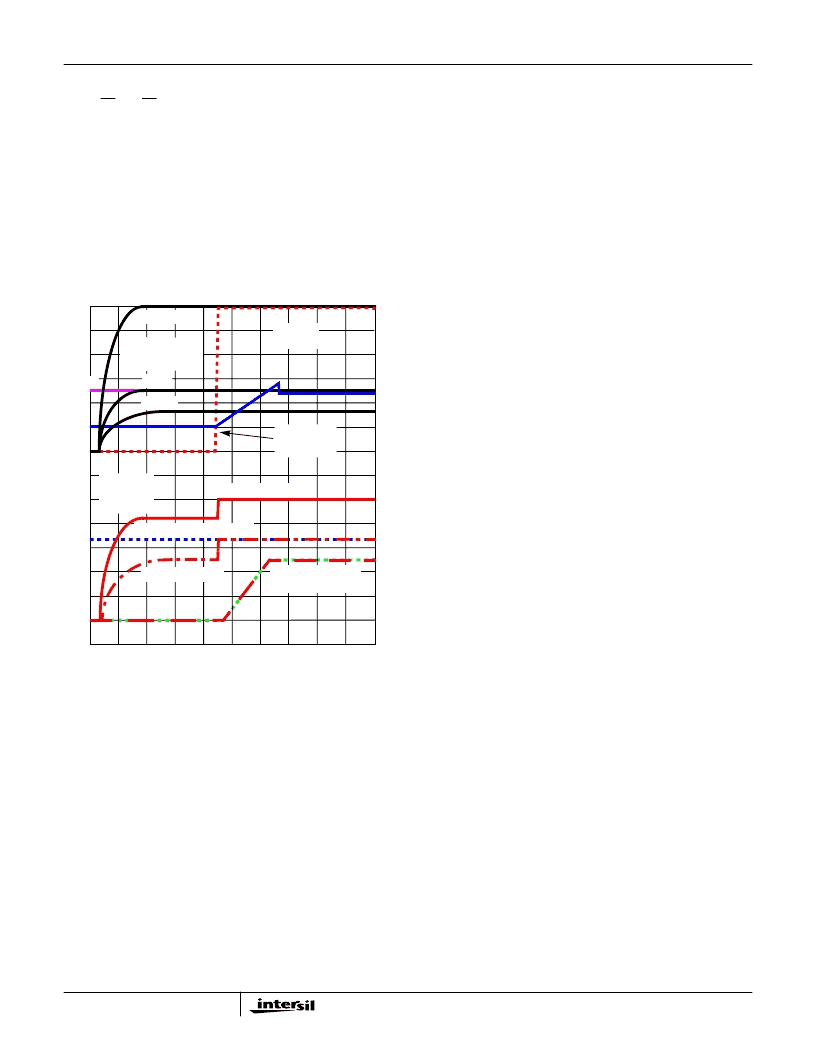
outputs. Figure 8 shows this start-up.
5VSB is already present when the main ATX outputs are
turned on at time T0. As a result of +3.3V
IN
and +5V
IN
ramping up, the 3.3V
MEM
and 5V
DUAL
output capacitors
charge up through the body diodes of Q6 and Q5,
respectively (see Figure 3). At time T1, all main ATX outputs
exceed the HIP6502’s undervoltage thresholds, and the
internal 25ms (typical) timer is initiated. At T2 the time-out
initiates a soft-start, and the 2.5V memory and clock outputs
are ramped-up, reaching regulation limits at time T3.
Simultaneous with the beginning of the memory and clock
voltage ramp-up, at time T2, the DLA pin is pulled high,
turning on Q3, Q5, and Q6 in the process, and bringing the
3.3V
MEM
and 5V
DUAL
outputs in regulation. Shortly after
time T3, as the SS voltage reaches 2.75V, the soft-start
capacitor is quickly discharged down to approximately 2.45V,
where it remains until a valid sleep state request is received
from the system.
It is important to note that in the typical application (as
pictured in Figure 3) the 3.3V memory output is powered up
during active state operation, regardless of the MSEL pin
status. Sleep state support on this output is, however,
dependent on the MSEL status.
Fault Protection
All the outputs are monitored against undervoltage events. A
severe overcurrent caused by a failed load on any of the
outputs, would, in turn, cause that specific output to
suddenly drop. If any of the output voltages drop below 80%
(typical) of their set value, such event is reported by having
the FAULT pin pulled to 5V. Additionally, exceeding the
maximum current rating of an integrated regulator (output
with pass regulator on chip) can lead to output voltage
drooping; if excessive, this droop can ultimately trip the
under-voltage detector and send a FAULT signal to the
computer system.
A FAULT condition occurring on an output when controlled
through an external pass transistor will only set off the
FAULT flag, and it will not shut off or latch off any part of the
circuit. A FAULT condition occurring on an output when
controlled through an internal pass transistor, will set off the
FAULT flag, and it will shut off the faulting regulator only. If
shutdown or latch off of the entire circuit is desired in case of
a fault, regardless of the cause, this can be achieved by
externally pulling or latching the SS pin low. Pulling the SS
pin low will also force the FAULT pin to go low and reset an
internally latched-off output.
Special consideration is given to the initial start-up
sequence. If, following a 5VSB POR event, the
3.3V
DUAL
/3.3V
SB
output is ramped up and is subject to an
undervoltage event before the remainder of the controlled
voltages have been brought up, then the FAULT output goes
high and the entire IC latches off. Latch-off condition can be
reset by cycling the bias power (5VSB). Undervoltage events
on the 3.3V
DUAL
/3.3V
SB
output at any other times are
handled according to the description found in the second
paragraph under the current heading.
Another condition that could set off the FAULT flag is chip
over-temperature. If the HIP6502 reaches an internal
temperature of 140
o
C (typical), the FAULT flag is set off, but
the chip continues to operate until the temperature reaches
155
o
C (typical), when unconditional shutdown of all outputs
takes place. Operation resumes at 140
o
C and the
FIGURE 8. SOFT-START INTERVAL IN ACTIVE STATE
(2.5/3.3V
MEM
OUTPUT SHOWN IN 2.5V SETTING)
0V
0V
TIME
OUTPUT
VOLTAGES
(1V/DIV)
T1
T2
T3
T0
INPUT VOLTAGES
(2V/DIV)
+5V
IN
+12V
IN
+5VSB
V
OUT2, 4
V
OUT3
(3.3V
MEM
)
V
OUT1
(
3.3V
DUAL
/3.3V
SB
)
V
OUT5
(5V
DUAL
)
DLA PIN
(2V/DIV)
SOFT-START
(1V/DIV)
(2.5V
MEM
, 2.5V
CLK
)
+3.3V
IN
HIP6502
相关PDF资料 |
PDF描述 |
|---|---|
| HIP6502CB | Multiple Linear Power Controller with ACPI Control Interface |
| HIP6503EVAL1 | Multiple Linear Power Controller with ACPI Control Interface |
| HIP6503CB | Circular Connector; No. of Contacts:37; Series:MS27467; Body Material:Aluminum; Connecting Termination:Crimp; Connector Shell Size:15; Circular Contact Gender:Socket; Circular Shell Style:Straight Plug; Insert Arrangement:15-35 |
| HIP6503 | Multiple Linear Power Controller with ACPI Control Interface(集成了多个线性电源控制器的芯片(ACPI控制接口)) |
| HIP6602ACB | FPGA 1600000 SYSTEM GATE 1.8 VOLT - NOT RECOMMENDED for NEW DESIGN |
相关代理商/技术参数 |
参数描述 |
|---|---|
| HIP6502 WAF | 制造商:Intersil Corporation 功能描述: |
| HIP6502_00 | 制造商:INTERSIL 制造商全称:Intersil Corporation 功能描述:Multiple Linear Power Controller with ACPI Control Interface |
| HIP6502B | 制造商:INTERSIL 制造商全称:Intersil Corporation 功能描述:Multiple Linear Power Controller with ACPI Control Interface |
| HIP6502BCB | 制造商:Rochester Electronics LLC 功能描述:- Bulk |
| HIP6502BEVAL1 | 制造商:INTERSIL 制造商全称:Intersil Corporation 功能描述:Multiple Linear Power Controller with ACPI Control Interface |
发布紧急采购,3分钟左右您将得到回复。