- 您现在的位置:买卖IC网 > PDF目录385382 > HIP6503CB (INTERSIL CORP) Circular Connector; No. of Contacts:37; Series:MS27467; Body Material:Aluminum; Connecting Termination:Crimp; Connector Shell Size:15; Circular Contact Gender:Socket; Circular Shell Style:Straight Plug; Insert Arrangement:15-35 PDF资料下载
参数资料
| 型号: | HIP6503CB |
| 厂商: | INTERSIL CORP |
| 元件分类: | 电源管理 |
| 英文描述: | Circular Connector; No. of Contacts:37; Series:MS27467; Body Material:Aluminum; Connecting Termination:Crimp; Connector Shell Size:15; Circular Contact Gender:Socket; Circular Shell Style:Straight Plug; Insert Arrangement:15-35 |
| 中文描述: | 9-CHANNEL POWER SUPPLY SUPPORT CKT, PDSO20 |
| 封装: | PLASTIC, MS-013-AC, SOIC-20 |
| 文件页数: | 10/14页 |
| 文件大小: | 151K |
| 代理商: | HIP6503CB |
10
In HIP6503 applications, loss of any one active ATX output
(3.3V
IN
, 5V
IN
, or 12V
IN
; as detected by the on-board voltage
monitors) during active state operation causes the chip to
switch to S5 sleep state, in addition to reporting the input UV
condition on the FAULT/MSEL pin. Exiting from this forced-
S5 state can only be achieved by returning the faulting input
voltage above its UV threshold, by resetting the chip through
removal of 5V
SB
bias voltage, or by bringing the SS pin at a
potential lower than 0.8V.
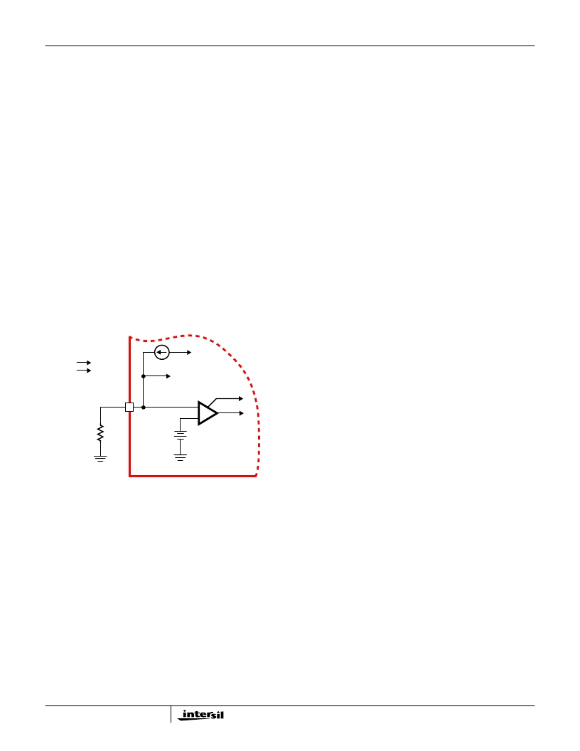
Output Voltages
The output voltages are internally set and do not require any
external components. Selection of the V
MEM
memory
voltage is done by means of an external resistor connected
between the FAULT/MSEL pin and ground. An internal 40
μ
A
(typical) current source creates a voltage drop across this
resistor. Following every 3.3V
SB
ramp-up or chip reset (see
Soft-Start Circuit), this voltage is compared with an internal
reference and the setting is latched in. Based on this
comparison, the output voltage is set at either 2.5V
(R
SEL
= 1k
), or 3.3V (R
SEL
= 10k
). It is very important
that no capacitor is connected to the FAULT/MSEL pin; the
presence of a capacitive element at this pin can lead to false
memory voltage selection. See Figure 9 for details.
Application Guidelines
Soft-Start Interval
The 5VSB output of a typical ATX supply is capable of
725mA. During power-up in a sleep state, it needs to provide
sufficient current to charge up all the output capacitors and
simultaneously provide some amount of current to the output
loads. Drawing excessive amounts of current from the 5VSB
output of the ATX can lead to voltage collapse and induce a
pattern of consecutive restarts with unknown effects on the
system’s behavior or health.
The built-in soft-start circuitry allows tight control of the slew-
up speed of the output voltages controlled by the HIP6503,
thus enabling power-ups free of supply drop-off events.
Since the outputs are ramped up in a linear fashion, the
current dedicated to charging the output capacitors can be
calculated with the following formula:
, where
I
SS
- soft-start current (typically 10
μ
A)
C
SS
- soft-start capacitor
V
BG
- bandgap voltage (typically 1.26V)
Σ
(
C
OUT
x V
OUT
) - sum of the products between the
capacitance and the voltage of an output (total charge
delivered to all outputs)
Due to the various system timing events, it is recommended
that the soft-start interval not be set to exceed 30ms.
Shutdown
In case of a FAULT condition that might endanger the
computer system, or at any other time, all the HIP6503
outputs can be shut down by pulling the SS pin below the
specified shutdown level (typically 0.8V) with an open drain
or open collector device capable of sinking a minimum of
2mA. Pulling the SS pin low effectively shuts down all the
pass elements. Upon release of the SS pin, the HIP6503
undergoes a new soft-start cycle and resumes normal
operation in accordance to the ATX supply and control pins
status.
Layout Considerations
The typical application employing a HIP6503 is a fairly
straight forward implementation. Like with any other linear
regulator, attention has to be paid to the few potentially
sensitive small signal components, such as those connected
to sensitive nodes or those supplying critical by-pass
current.
The power components (pass transistors) and the controller
IC should be placed first. The controller should be placed in
a central position on the motherboard, closer to the memory
load if possible, but not excessively far from the clock chip or
the processor. Insure the 1V8SB, DRV2 and VSEN2
connections are properly sized to carry 250mA without
significant resistive losses; similar guideline applies to the
VCLK output, which can deliver as much as 800mA (typical).
As the current for the VCLK output is provided from the ATX
3.3V, the connection from the 3V3 pin to the 3.3V plane
should be sized to carry the maximum clock output current
while exhibiting negligible voltage losses. Similarly, the 5VSB
and the 5V pins are carrying significant levels of current - for
best results, insure they are connected to their respective
sources through adequately sized traces. The pass
transistors should be placed on pads capable of heatsinking
matching the device’s power dissipation. Where applicable,
multiple via connections to a large internal plane can
significantly lower localized device temperature rise.
Placement of the decoupling and bulk capacitors should
follow a placement reflecting their purpose. As such, the
FIGURE 9. 2.5/3.3V
MEM
OUTPUT VOLTAGE SELECTION
CIRCUITRY DETAILS
FAULT/MSEL
40
μ
A
+
-
+
-
0.2V
MEM VOLTAGE
SELECT COMP
R
SEL
R
SEL
1k
10k
V
MEM
2.5V
3.3V
5VSB
I
COUT
I
SS
BG
-----------------------------
Σ
C
OUT
V
OUT
×
(
)
×
=
HIP6503
相关PDF资料 |
PDF描述 |
|---|---|
| HIP6503 | Multiple Linear Power Controller with ACPI Control Interface(集成了多个线性电源控制器的芯片(ACPI控制接口)) |
| HIP6602ACB | FPGA 1600000 SYSTEM GATE 1.8 VOLT - NOT RECOMMENDED for NEW DESIGN |
| HIP6602ACR | FPGA 1600000 SYSTEM GATE 1.8 VOLT - NOT RECOMMENDED for NEW DESIGN |
| HIP6602ACR-T | FPGA 1600000 SYSTEM GATE 1.8 VOLT - NOT RECOMMENDED for NEW DESIGN |
| HIP6602ACB-T | Dual Channel Synchronous Rectified Buck MOSFET Driver |
相关代理商/技术参数 |
参数描述 |
|---|---|
| HIP6503CBZ | 功能描述:PMIC 解决方案 W/ANNEAL ACPI PWR MANAGEMNT CIRCUIT RoHS:否 制造商:Texas Instruments 安装风格:SMD/SMT 封装 / 箱体:QFN-24 封装:Reel |
| HIP6503CBZ-T | 功能描述:PMIC 解决方案 W/ANNEAL ACPI PWR MG T CIRCUIT 20LD RoHS:否 制造商:Texas Instruments 安装风格:SMD/SMT 封装 / 箱体:QFN-24 封装:Reel |
| HIP6503CR | 制造商:未知厂家 制造商全称:未知厂家 功能描述:Analog IC |
| HIP6503EVAL1 | 制造商:INTERSIL 制造商全称:Intersil Corporation 功能描述:Multiple Linear Power Controller with ACPI Control Interface |
| HIP6521 | 制造商:INTERSIL 制造商全称:Intersil Corporation 功能描述:PWM and Triple Linear Power Controller |
发布紧急采购,3分钟左右您将得到回复。