参数资料
| 型号: | HL2-PS-K |
| 厂商: | Panasonic Electric Works |
| 文件页数: | 3/7页 |
| 文件大小: | 0K |
| 描述: | SOCKET TERM PCB FOR HL2 RELAY |
| 标准包装: | 20 |
| 系列: | HL |
| 类型: | 插口 |
| 位置数: | 8 |
| 安装类型: | 通孔 |
| 端接类型: | PC 引脚 |
| 适用于相关产品: | HL2 继电器 |
| 产品目录页面: | 2607 (CN2011-ZH PDF) |
| 配用: | 255-2798-ND - RELAY GEN PURPOSE DPDT 10A 24V 255-2796-ND - RELAY GEN PURPOSE DPDT 10A 115V HL2-L-AC100V-F-ND - RELAY GEN PURPOSE DPDT 10A 100V 255-2795-ND - RELAY GEN PURPOSE DPDT 10A 100V HL2-H-DC48V-F-ND - RELAY GEN PURPOSE DPDT 10A 48V 255-2801-ND - RELAY GEN PURPOSE DPDT 10A 24V 255-2799-ND - RELAY GEN PURPOSE DPDT 10A 12V HL2-H-AC240V-F-ND - RELAY GEN PURPOSE DPDT 10A 240V 255-2797-ND - RELAY GEN PURPOSE DPDT 10A 120V HL2-H-DC6V-F-ND - RELAY GEN PURPOSE DPDT 10A 6V |
| 其它名称: | 255-2218 HL2-PS-K-ND |
�� �
�
�HL�
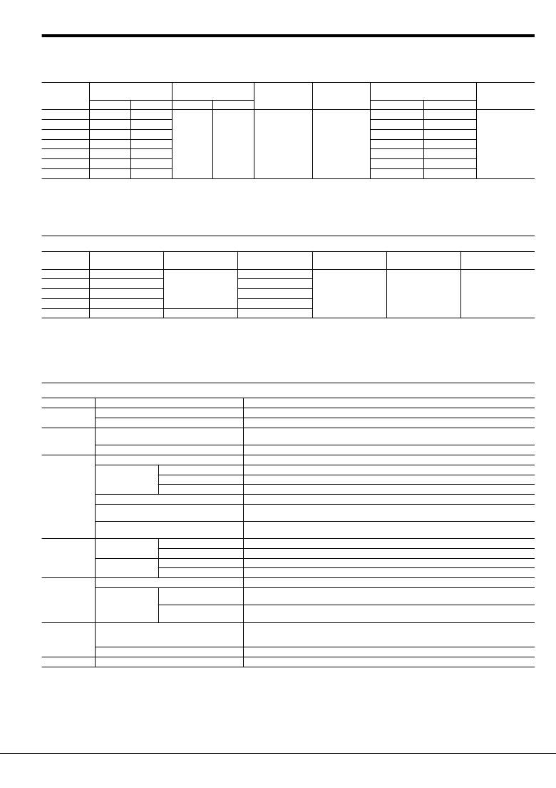
�RATING�
�1.� Coil� data�
�1)� AC� coils�
�Nominal� coil�
�voltage�
�6V� AC�
�12V� AC�
�Nominal� coil� current�
�(mA)�
�50Hz� 60Hz�
�224�
�200�
�111�
�100�
�Nominal� operating� power�
�(VA)�
�50Hz� 60Hz�
�Pick-up� voltage�
�(at� 20� °� C� 68� °� F� )�
�Drop-out� voltage�
�(at� 20� °� C� 68� °� F� )�
�Inductance� (H)�
�When� drop-out� When� operating�
�0.078�
�0.074�
�0.312�
�0.295�
�Max.� applied�
�voltage�
�(at� 70� °� C� 158� °� F� )�
�24V� AC�
�48V� AC�
�100/110V� AC�
�56�
�28�
�13.4/14.7�
�50�
�25�
�12/13.2�
�1.3�
�1.2�
�80%V� or� less� of�
�nominal� voltage�
�(Initial)�
�30%V� or� more� of�
�nominal� voltage�
�(Initial)�
�1.243�
�4.974�
�23.75�
�1.181�
�4.145�
�20.63�
�110%V� of�
�nominal� voltage�
�110/120V� AC�
�200/220V� AC�
�12.2/13.5�
�6.7/7.4�
�10.9/11.9�
�6/6.6�
�27.19�
�85.98�
�25.57�
�81.76�
�Notes:� 1.� The� relay� operates� in� a� range� of� 80%� to� 110%� V� of� the� nominal� voltage,� but� ideally,� in� consideration� of� temporary� voltage� ?uctuations,� it� should� be� operated� at� the�
�rated� voltage.�
�In� particular,� for� AC� operation,� if� the� applied� voltage� drops� to� 80%� V� or� more� below� the� nominal� voltage,� humming� will� occur� and� a� large� current� will� ?ow� leading�
�possibly� to� coil� burnout.�
�2.� The� maximum� applied� voltage� is� the� maximum� voltage� ?uctuation� value� for� the� coil� power� supply.� This� value� is� not� a� permissible� value� for� continuous� operation.�
�(This� value� differs� depending� on� the� ambient� temperature.� Please� contact� us� for� details.)�
�2)� DC� coils� (at� 20� °� C� 68� °� F� )�
�Nominal� coil�
�voltage�
�Nominal� coil� current�
�(mA)�
�Nominal� operating�
�power� (W)�
�Coil� resistance�
�(� ?� )�
�Pick-up� voltage�
�(at� 20� °� C� 68� °� F� )�
�Drop-out� voltage�
�(at� 20� °� C� 68� °� F� )�
�Max.� applied� voltage�
�(at� 70� °� C� 158� °� F� )�
�6V� DC�
�150�
�40�
�12V� DC�
�24V� DC�
�48V� DC�
�75�
�37�
�18.5�
�0.9�
�160�
�650�
�2,600�
�80%V� or� less� of�
�nominal� voltage�
�(Initial)�
�10%V� or� more� of�
�nominal� voltage�
�(Initial)�
�110%V� of�
�nominal� voltage�
�100/110V� DC�
�10�
�1.0�
�10,000�
�Notes:� 1.� The� nominal� operating� current� is� ±� 10%� (20� °� C� 68� °� F� ).�
�2.� The� coil� resistance� for� DC� operation� is� the� value� measured� when� the� coil� temperature� is� 20� °� C� 68� °� F� .� Compensate� ±� 0.4%� for� every� ±� 1� °� C� change� in� temperature.�
�3.� The� relay� operates� in� a� range� of� 80%� to� 110%� V� of� the� nominal� voltage,� but� ideally,� in� consideration� of� temporary� voltage� ?uctuations,� it� should� be� operated� at� the�
�nominal� voltage.�
�4.� For� use� with� 200� V� DC,� connect� a� 10� K� ?� (5W)� resistor,� in� series,� to� the� 100� V� DC� relay.�
�5.� The� maximum� applied� voltage� is� the� maximum� voltage� ?uctuation� value� for� the� coil� power� supply.� This� value� is� not� a� permissible� value� for� continuous� operation.�
�(This� value� differs� depending� on� the� ambient� temperature.� Please� contact� us� for� details.)�
�2.� Speci?cations�
�Characteristics�
�Contact�
�Rating�
�Item�
�Contact� resistance� (Initial)�
�Contact� material�
�Nominal� switching� capacity*� 4�
�Min.� switching� capacity� (Reference� value)*� 1�
�Insulation� resistance� (Initial)�
�Between� open� contacts�
�Speci?cations�
�Max.� 50� m� ?� (By� voltage� drop� 6� V� DC� 1A)�
�AgSnO� 2� type�
�1� Form� C:� 15A� 125V� AC,� 10A� 250V� AC� (resistive� load)�
�2� Form� C:� 10A� 250V� AC� (resistive� load)�
�100mA� 5V� DC�
�Min.� 100M� ?� (at� 500V� DC)� Measurement� at� same� location� as� “Breakdown� voltage”� section.�
�1,000� Vrms� for� 1min.� (Detection� current:� 10mA)�
�Breakdown� voltage�
�(Initial)�
�Between� contact� sets�
�1,500� Vrms� for� 1min.� (Detection� current:� 10mA)�
�Electrical�
�characteristics�
�Between� contact� and� coil�
�Temperature� rise� (coil)�
�Operate� time� (at� 20� °� C� 68� °� F� )*� 2�
�Release� time� (at� 20� °� C� 68� °� F� )*� 2�
�2,000� Vrms� for� 1min.� (Detection� current:� 10mA)�
�Max.� 80� °� C� 176� °� F� (By� resistive� method,� nominal� voltage)�
�DC� type/AC� type:� Max.� 25ms�
�(Nominal� coil� voltage� applied� to� the� coil,� excluding� contact� bounce� time.)�
�DC� type/AC� type:� Max.� 25ms�
�(Nominal� coil� voltage� applied� to� the� coil,� excluding� contact� bounce� time.)� (without� diode)�
�Mechanical�
�characteristics�
�Expected� life�
�Shock� resistance�
�Vibration� resistance�
�Mechanical�
�Electrical�
�Functional�
�Destructive�
�Functional�
�Destructive�
�AC� load�
�DC� load�
�Min.� 196� m/s� 2� (Half-wave� pulse� of� sine� wave:� 11� ms;� detection� time:� 10� μ� s.)�
�Min.� 980� m/s� 2� (Half-wave� pulse� of� sine� wave:� 6� ms.)�
�10� to� 55� Hz� at� double� amplitude� of� 1� mm� (Detection� time:� 10� μ� s.)�
�10� to� 55� Hz� at� double� amplitude� of� 2� mm�
�AC� type:� 5� � 10� 7� (at� 180� times/min.),� DC� type:� 10� 8� (at� 180� times/min.)�
�1� Form� C:� 15A� 125V� AC,� 10A� 250V� AC� resistive� load� (cos� ?� =1)� Life� switching� cycle:� Min.� 5� � 10� 5�
�2� Form� C:� 10A� 250V� AC� resistive� load� (cos� ?� =1)� Life� switching� cycle:� Min.� 3� � 10� 5�
�1� Form� C:� 3A� 30V� DC� resistive� load� (cos� ?� =1)� Life� switching� cycle:� Min.� 5� � 10� 5�
�2� Form� C:� 3A� 30V� DC� resistive� load� (cos� ?� =1)� Life� switching� cycle:� Min.� 5� � 10� 5�
�Conditions�
�Conditions� for� operation,� transport� and� storage*� 3�
�Ambient� temperature:� –50� °� C� to� +70� °� C� –58� °� F� to� +158� °� F� (Without� LED� indication);�
�–50� °� C� to� +60� °� C� –58� °� F� to� +140� °� F� (With� LED� indication)�
�Humidity:� 5� to� 85%� R.H.� (Not� freezing� and� condensing� at� low� temperature)�
�Unit� weight�
�Max.� Operating� speed�
�20� times/min.� (at� max.� rating)�
�Approx.� 35g� 1.23� oz�
�Notes:� If� integrating� into� electrical� appliances� that� will� be� subject� to� compliance� to� the� Electrical� Appliance� and� Material� Safety� Law,� please� use� in� an� ambient� temperature�
�between� –50� °� C� to� +40� °� C� –58� °� F� to� +104� °� F� (AC� type).�
�*1.� This� value� can� change� due� to� the� switching� frequency,� environmental� conditions� and� desired� reliability� level,� therefore� it� is� recommended� to� check� this� with� the�
�actual� load.�
�*2.� For� the� AC� coil� types,� the� operate/release� time� will� differ� depending� on� the� phase.�
�*3.� The� upper� limit� of� the� ambient� temperature� is� the� maximum� temperature� that� can� satisfy� the� coil� temperature� rise� value.� Refer� to� Usage,� transport� and� storage�
�conditions� in� NOTES.�
�*4.� When� using� the� socket,� be� sure� to� verify� the� max.� continuous� current.�
�Panasonic� Corporation� Automation� Controls� Buisiness� Division�
�industrial.panasonic.com/ac/e/�
�–3–�
�?� Panasonic� Corporation� 2013�
�ASCTB114E� 201305-T�
�相关PDF资料 |
PDF描述 |
|---|---|
| 0ZCA0075FF2G | PTC RESTTBLE 0.75A 6V CHIP 1206 |
| 0ZCE0035FF2G | PTC RESTTBLE 0.35A 6V CHIP 0805 |
| 0ZCE0010FF2G | PTC RESTTBLE 0.10A 15V CHIP 0805 |
| 430210-09-0 | TERM BARRIER 9CIRC SGL ROW .4375 |
| 430412-08-0 | TERM BARRIER 8CIRC SGL ROW .4375 |
相关代理商/技术参数 |
参数描述 |
|---|---|
| HL2-PS-K-F | 制造商:Panasonic Electric Works 功能描述: |
| HL2PSKJ | 制造商:Panasonic Electric Works 功能描述: |
| HL2-SFDK | 制造商:Panasonic 功能描述:Bulk |
| HL2-SFD-K | 功能描述:继电器插座与硬件 FOR HL2 RELAYS SCREW DIN RoHS:否 制造商:TE Connectivity / Schrack 附件类型:Socket 相关继电器系列:RP, RT, RY 端接类型:PCB 极数:1 |
| HL2SFDKJ | 制造商:Panasonic Electric Works 功能描述: |
发布紧急采购,3分钟左右您将得到回复。