- 您现在的位置:买卖IC网 > PDF目录385385 > HLMP-HD57-NR0xx (Avago Technologies Ltd.) 5 mm Standard Oval Precision Optical Performance Red LED PDF资料下载
参数资料
| 型号: | HLMP-HD57-NR0xx |
| 厂商: | Avago Technologies Ltd. |
| 英文描述: | 5 mm Standard Oval Precision Optical Performance Red LED |
| 中文描述: | 5毫米标准椭圆形精密光学性能红色LED |
| 文件页数: | 5/8页 |
| 文件大小: | 323K |
| 代理商: | HLMP-HD57-NR0XX |
Precautions:
Lead Forming:
The leads of an LED lamp may be preformed or cut to
length prior to insertion and soldering on PC board.
For better control, it is recommended to use proper
tool to precisely form and cut the leads to applicable
length rather than doing it manually.
If manual lead cutting is necessary, cut the leads after
the soldering process. The solder connection forms a
mechanical ground which prevents mechanical stress
due to lead cutting from traveling into LED package.
This is highly recommended for hand solder operation,
as the excess lead length also acts as small heat sink.
Soldering and Handling:
Care must be taken during PCB assembly and soldering
process to prevent damage to the LED component.
LED component may be effectively hand soldered
to PCB. However, it is only recommended under
unavoidable circumstances such as rework. The closest
manual soldering distance of the soldering heat source
(soldering iron’s tip) to the body is 1.59mm. Soldering
the LED using soldering iron tip closer than 1.59mm
might damage the LED.
Note:
1. PCB with different size and design (component density) will have
different heat mass (heat capacity). This might cause a change in
temperature experienced by the board if same wave soldering
setting is used. So, it is recommended to re-calibrate the soldering
profile again before loading a new type of PCB.
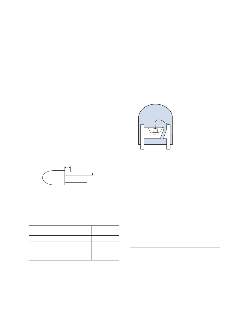
. Avago Technologies’ high brightness LED are using high efficiency
LED die with single wire bond as shown below. Customer is advised
to take extra precaution during wave soldering to ensure that the
maximum wave temperature does not exceed 50°C and the solder
contact time does not exceeding 3sec. Over-stressing the LED during
soldering process might cause premature failure to the LED due to
delamination.
Avago Technologies LED configuration
1.59mm
ESD precaution must be properly applied on the
soldering station and personnel to prevent ESD
damage to the LED component that is ESD sensitive.
Do refer to Avago application note AN 114 for details.
The soldering iron used should have grounded tip to
ensure electrostatic charge is properly grounded.
Recommended soldering condition:
Wave
Soldering
[1, 2]
105 °C Max.
60 sec Max
250 °C Max.
3 sec Max.
Manual Solder
Dipping
-
-
260 °C Max.
5 sec Max
Pre-heat temperature
Preheat time
Peak temperature
Dwell time
Note:
1) Above conditions refers to measurement with thermocouple
mounted at the bottom of PCB.
) It is recommended to use only bottom preheaters in order to reduce
thermal stress experienced by LED.
Wave soldering parameters must be set and maintained
according to the recommended temperature and dwell
time. Customer is advised to perform daily check on the
soldering profile to ensure that it is always conforming
to recommended soldering conditions.
Note: Electrical connection between bottom surface of LED die and
the lead frame is achieved through conductive paste.
Any alignment fixture that is being applied during
wave soldering should be loosely fitted and should
not apply weight or force on LED. Non metal material
is recommended as it will absorb less heat during wave
soldering process.
At elevated temperature, LED is more susceptible to
mechanical stress. Therefore, PCB must allowed to cool
down to room temperature prior to handling, which
includes removal of alignment fixture or pallet.
If PCB board contains both through hole (TH) LED and
other surface mount components, it is recommended
that surface mount components be soldered on the
top side of the PCB. If surface mount need to be on the
bottom side, these components should be soldered
using reflow soldering prior to insertion the TH LED.
Recommended PC board plated through holes (PTH)
size for LED component leads.
LED component
lead size
0.45 x 0.45 mm
(0.018x 0.018 inch)
0.50 x 0.50 mm
(0.020x 0.020 inch)
Diagonal
0.636 mm
(0.025 inch)
0.707 mm
(0.028 inch)
Plated through
hole diameter
0.98 to 1.08 mm
(0.039 to 0.043 inch)
1.05 to 1.15 mm
(0.041 to 0.045 inch)
Over-sizing the PTH can lead to twisted LED after
clinching. On the other hand under sizing the PTH can
cause difficulty inserting the TH LED.
CATHODE
相关PDF资料 |
PDF描述 |
|---|---|
| HLMP-LB11 | 4 mm Precision Optical Performance InGaN Standard Oval LED Lamps |
| HLMP-LB11-FJ0xx | 4 mm Precision Optical Performance InGaN Standard Oval LED Lamps |
| HLMP-LB11-HJCxx | 4 mm Precision Optical Performance InGaN Standard Oval LED Lamps |
| HLMP-LB11-HL0xx | 4 mm Precision Optical Performance InGaN Standard Oval LED Lamps |
| HLMP-LB11-JKCxx | 4 mm Precision Optical Performance InGaN Standard Oval LED Lamps |
相关代理商/技术参数 |
参数描述 |
|---|---|
| HLMP-HD57-NR0ZZ | 功能描述:标准LED-通孔 Red 40x100deg d 40X100deg RoHS:否 制造商:Vishay Semiconductors 照明颜色:Red 光强度:0.7 mcd 波长/色温:615 nm 显示角:45 deg 透镜颜色/类型:Clear, Non-Diffused 正向电流:70 mA 正向电压:1.83 V to 3.03 V LED 大小:2 mm 系列: 封装:Tube |
| HLMP-HD60-TUTDD | 功能描述:标准LED-通孔 Red 40x100 Degrees RoHS:否 制造商:Vishay Semiconductors 照明颜色:Red 光强度:0.7 mcd 波长/色温:615 nm 显示角:45 deg 透镜颜色/类型:Clear, Non-Diffused 正向电流:70 mA 正向电压:1.83 V to 3.03 V LED 大小:2 mm 系列: 封装:Tube |
| HLMP-HD61-TWTYY | 功能描述:标准LED-通孔 Red 40x100deg d 40X100deg RoHS:否 制造商:Vishay Semiconductors 照明颜色:Red 光强度:0.7 mcd 波长/色温:615 nm 显示角:45 deg 透镜颜色/类型:Clear, Non-Diffused 正向电流:70 mA 正向电压:1.83 V to 3.03 V LED 大小:2 mm 系列: 封装:Tube |
| HLMP-HD61-TXTZZ | 功能描述:标准LED-通孔 Red 40x100deg d 40X100deg RoHS:否 制造商:Vishay Semiconductors 照明颜色:Red 光强度:0.7 mcd 波长/色温:615 nm 显示角:45 deg 透镜颜色/类型:Clear, Non-Diffused 正向电流:70 mA 正向电压:1.83 V to 3.03 V LED 大小:2 mm 系列: 封装:Tube |
| HLMP-HG62-TX0DD | 功能描述:标准LED-通孔 Red 40x100deg RoHS:否 制造商:Vishay Semiconductors 照明颜色:Red 光强度:0.7 mcd 波长/色温:615 nm 显示角:45 deg 透镜颜色/类型:Clear, Non-Diffused 正向电流:70 mA 正向电压:1.83 V to 3.03 V LED 大小:2 mm 系列: 封装:Tube |
发布紧急采购,3分钟左右您将得到回复。