- 您现在的位置:买卖IC网 > Datasheet目录863 > HPH-12/30-D48NB-C (Murata Power Solutions Inc)CONV DC/DC 12V 30A 360W Datasheet资料下载
参数资料
| 型号: | HPH-12/30-D48NB-C |
| 厂商: | Murata Power Solutions Inc |
| 文件页数: | 10/13页 |
| 文件大小: | 0K |
| 描述: | CONV DC/DC 12V 30A 360W |
| 标准包装: | 36 |
| 系列: | HPH |
| 类型: | 隔离 |
| 输出数: | 1 |
| 电压 - 输入(最小): | 36V |
| 电压 - 输入(最大): | 75V |
| Voltage - Output 1: | 12V |
| 电流 - 输出(最大): | 30A |
| 电源(瓦) - 制造商系列: | 360W |
| 电压 - 隔离: | 2.25kV(2250V) |
| 安装类型: | 通孔 |
| 封装/外壳: | 9-DIP 模块,1/2 砖 |
| 尺寸/尺寸: | 2.40" L x 2.30" W x 0.40" H(61.0mm x 58.4mm x 10.2mm) |
| 包装: | 管件 |
| 工作温度: | -40°C ~ 85°C |
| 效率: | 93% |
| 电源(瓦特)- 最大: | 360W |
| 产品目录页面: | 2719 (CN2011-ZH PDF) |
| 其它名称: | 811-1753-5 |
�� �
�
�HPH� Series�
�Isolated,� Low� V� OUT� to� 70A,� Half-Brick� DC/DC� Converters�
�Note� that� the� temperatures� are� of� the� ambient� air?ow,� not� the� converter� itself�
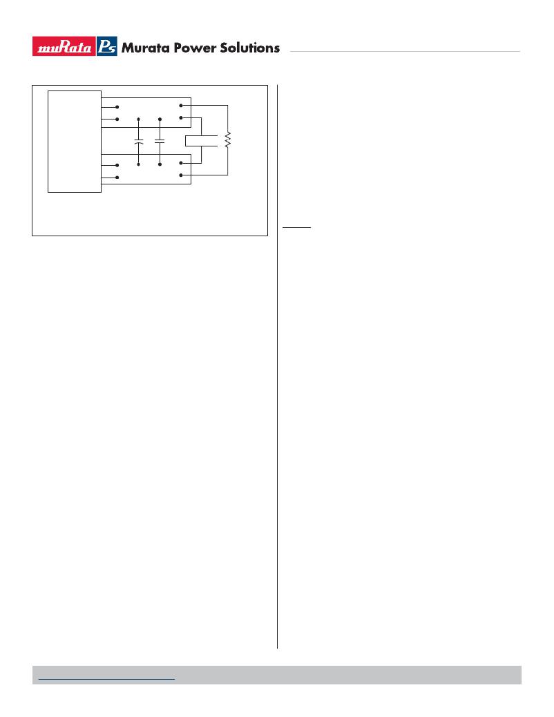
�+SENSE�
�+OUTPUT�
�6�
�5�
�COPPER� STRIP�
�which� is� obviously� running� at� higher� temperature� than� the� outside� air.� Also� note�
�that� very� low� ?ow� rates� (below� about� 25� LFM)� are� similar� to� “natural� convec-�
�tion”,� that� is,� not� using� fan-forced� air?ow.�
�-OUTPUT�
�-SENSE�
�9�
�8�
�C1�
�COPPER� STRIP�
�C2�
�SCOPE�
�R� LOAD�
�MPS� makes� Characterization� measurements� in� a� closed� cycle� wind� tunnel� with�
�calibrated� air?ow.� We� use� both� thermocouples� and� an� infrared� camera� system�
�to� observe� thermal� performance.� As� a� practical� matter,� it� is� quite� dif?cult� to�
�insert� an� anemometer� to� precisely� measure� air?ow� in� most� applications.�
�Sometimes� it� is� possible� to� estimate� the� effective� air?ow� if� you� thoroughly� un-�
�derstand� the� enclosure� geometry,� entry/exit� ori?ce� areas� and� the� fan� ?owrate�
�C1� =� 0.1μF� CERAMIC�
�C2� =� 10μF� TANTALUM�
�LOAD� 2-3� INCHES� (51-76mm)� FROM� MODULE�
�Figure� 3.� Measuring� Output� Ripple� and� Noise� (PARD)�
�Floating� Outputs�
�Since� these� are� isolated� DC/DC� converters,� their� outputs� are� “?oating”� with�
�respect� to� their� input.� The� essential� feature� of� such� isolation� is� ideal� ZERO�
�CURRENT� FLOW� between� input� and� output.� Real-world� converters� however� do�
�exhibit� tiny� leakage� currents� between� input� and� output� (see� Speci?cations).�
�These� leakages� consist� of� both� an� AC� stray� capacitance� coupling� component�
�and� a� DC� leakage� resistance.� When� using� the� isolation� feature,� do� not� allow�
�the� isolation� voltage� to� exceed� speci?cations.� Otherwise� the� converter� may�
�be� damaged.� Designers� will� normally� use� the� negative� output� (-Output)� as�
�the� ground� return� of� the� load� circuit.� You� can� however� use� the� positive� output�
�(+Output)� as� the� ground� return� to� effectively� reverse� the� output� polarity.�
�Minimum� Output� Loading� Requirements�
�These� converters� employ� a� synchronous� recti?er� design� topology.� All� models�
�regulate� within� speci?cation� and� are� stable� under� no� load� to� full� load� condi-�
�tions.� Operation� under� no� load� might� however� slightly� increase� output� ripple�
�and� noise.�
�Thermal� Shutdown�
�To� prevent� many� over� temperature� problems� and� damage,� these� converters�
�include� thermal� shutdown� circuitry.� If� environmental� conditions� cause� the�
�temperature� of� the� DC/DC’s� to� rise� above� the� Operating� Temperature� Range�
�up� to� the� shutdown� temperature,� an� on-board� electronic� temperature� sensor�
�will� power� down� the� unit.� When� the� temperature� decreases� below� the� turn-on�
�threshold,� the� converter� will� automatically� restart.� There� is� a� small� amount� of�
�hysteresis� to� prevent� rapid� on/off� cycling.� The� temperature� sensor� is� typically�
�located� adjacent� to� the� switching� controller,� approximately� in� the� center� of� the�
�unit.� See� the� Performance� and� Functional� Speci?cations.�
�CAUTION:� If� you� operate� too� close� to� the� thermal� limits,� the� converter� may� shut�
�down� suddenly� without� warning.� Be� sure� to� thoroughly� test� your� application� to�
�avoid� unplanned� thermal� shutdown.�
�Temperature� Derating� Curves�
�The� graphs� in� this� data� sheet� illustrate� typical� operation� under� a� variety� of�
�conditions.� The� Derating� curves� show� the� maximum� continuous� ambient� air�
�temperature� and� decreasing� maximum� output� current� which� is� acceptable�
�under� increasing� forced� air?ow� measured� in� Linear� Feet� per� Minute� (“LFM”).�
�Note� that� these� are� AVERAGE� measurements.� The� converter� will� accept� brief�
�increases� in� temperature� and/or� current� or� reduced� air?ow� as� long� as� the� aver-�
�age� is� not� exceeded.�
�speci?cations.� If� in� doubt,� contact� MPS� to� discuss� placement� and� measurement�
�techniques� of� suggested� temperature� sensors.�
�CAUTION:� If� you� routinely� or� accidentally� exceed� these� Derating� guidelines,� the�
�converter� may� have� an� unplanned� Over� Temperature� shut� down.� Also,� these�
�graphs� are� all� collected� at� slightly� above� Sea� Level� altitude.� Be� sure� to� reduce�
�the� derating� for� higher� density� altitude.�
�Output� Overvoltage� Protection�
�This� converter� monitors� its� output� voltage� for� an� over-voltage� condition� using�
�an� on-board� electronic� comparator.� The� signal� is� optically� coupled� to� the� pri-�
�mary� side� PWM� controller.� If� the� output� exceeds� OVP� limits,� the� sensing� circuit�
�will� power� down� the� unit,� and� the� output� voltage� will� decrease.� After� a� time-out�
�period,� the� PWM� will� automatically� attempt� to� restart,� causing� the� output� volt-�
�age� to� ramp� up� to� its� rated� value.� It� is� not� necessary� to� power� down� and� reset�
�the� converter� for� this� automatic� OVP-recovery� restart.�
�If� the� fault� condition� persists� and� the� output� voltage� climbs� to� excessive� levels,�
�the� OVP� circuitry� will� initiate� another� shutdown� cycle.� This� on/off� cycling� is�
�referred� to� as� “hiccup”� mode.� It� safely� tests� full� current� rated� output� voltage�
�without� damaging� the� converter.�
�Output� Fusing�
�The� converter� is� extensively� protected� against� current,� voltage� and� temperature�
�extremes.� However� your� output� application� circuit� may� need� additional� protec-�
�tion.� In� the� extremely� unlikely� event� of� output� circuit� failure,� excessive� voltage�
�could� be� applied� to� your� circuit.� Consider� using� an� appropriate� fuse� in� series�
�with� the� output.�
�Output� Current� Limiting�
�As soon as the output current increases to approximately 125% to 150% of�
�its� maximum� rated� value,� the� DC/DC� converter� will� enter� a� current-limiting�
�mode.� The� output� voltage� will� decrease� proportionally� with� increases� in� output�
�current,� thereby� maintaining� a� somewhat� constant� power� output.� This� is� com-�
�monly� referred� to� as� power� limiting.�
�Current� limiting� inception� is� de?ned� as� the� point� at� which� full� power� falls� below�
�the� rated� tolerance.� See� the� Performance/Functional� Speci?cations.� Note�
�particularly� that� the� output� current� may� brie?y� rise� above� its� rated� value.� This�
�enhances� reliability� and� continued� operation� of� your� application.� If� the� output�
�current� is� too� high,� the� converter� will� enter� the� short� circuit� condition.�
�Output� Short� Circuit� Condition�
�When� a� converter� is� in� current-limit� mode,� the� output� voltage� will� drop� as�
�the� output� current� demand� increases.� If� the� output� voltage� drops� too� low,� the�
�magnetically� coupled� voltage� used� to� develop� primary� side� voltages� will� also�
�drop,� thereby� shutting� down� the� PWM� controller.� Following� a� time-out� period,�
�www.murata-ps.com/support�
�MDC_HPH_B01� Page� 10� of� 13�
�相关PDF资料 |
PDF描述 |
|---|---|
| HPQ-12/25-D48PBH-C | CONV DC/DC 300W 12V 25A POS LOG |
| HPQ-3.3/50-D48NB-C | CONV DC/DC 165W 3.3V 50A |
| HPR100WC | CONV DC/DC SGL 5V 150MA SMD |
| HPR1023C | CONV DC/DC +/-15V +/-34MA SIP |
| HPR103C | CONV DC/DC +/-5V +/-75MA SIP |
相关代理商/技术参数 |
参数描述 |
|---|---|
| HPH1-A | 制造商:ADAM-TECH 制造商全称:Adam Technologies, Inc. 功能描述:.050 PIN HEADERS .050 [1.27] CENTERLINE |
| HPH1A01SGA | 制造商:ADAM-TECH 制造商全称:Adam Technologies, Inc. 功能描述:.050 PIN HEADERS .050 [1.27] CENTERLINE |
| HPH1A01SGB | 制造商:ADAM-TECH 制造商全称:Adam Technologies, Inc. 功能描述:.050 PIN HEADERS .050 [1.27] CENTERLINE |
| HPH1A01TA | 制造商:ADAM-TECH 制造商全称:Adam Technologies, Inc. 功能描述:.050 PIN HEADERS .050 [1.27] CENTERLINE |
| HPH1A01TB | 制造商:ADAM-TECH 制造商全称:Adam Technologies, Inc. 功能描述:.050 PIN HEADERS .050 [1.27] CENTERLINE |
发布紧急采购,3分钟左右您将得到回复。