- 您现在的位置:买卖IC网 > PDF目录8065 > HPQ-12/25-D48NBL1-C (Murata Power Solutions Inc)CONV DC/DC 300W 12V 25A PDF资料下载
参数资料
| 型号: | HPQ-12/25-D48NBL1-C |
| 厂商: | Murata Power Solutions Inc |
| 文件页数: | 12/16页 |
| 文件大小: | 0K |
| 描述: | CONV DC/DC 300W 12V 25A |
| 标准包装: | 60 |
| 系列: | * |
| 其它名称: | HPQ-12/25-D48NBL1C HPQ-12/25-D48NBL1C-ND Q7059696A |
�� �
�
�HPQ-12/25-D48� Series�
�Isolated� 300-Watt� Quarter� Brick� DC-DC� Converters�
�TECHNICAL� NOTES�
�Input� Fusing�
�Certain� applications� and/or� safety� agencies� may� require� fuses� at� the� inputs� of�
�power� conversion� components.� Fuses� should� also� be� used� when� there� is� the�
�possibility� of� sustained� input� voltage� reversal� which� is� not� current-limited.� For�
�greatest� safety,� we� recommend� a� fast� blow� fuse� installed� in� the� ungrounded�
�input� supply� line.�
�The� installer� must� observe� all� relevant� safety� standards� and� regulations.� For�
�safety� agency� approvals,� install� the� converter� in� compliance� with� the� end-user�
�safety� standard.�
�Input� Reverse-Polarity� Protection�
�If� the� input� voltage� polarity� is� reversed,� body� diodes� of� mosfets� will� become�
�forward� biased� and� likely� draw� excessive� current� from� the� power� source.� If� this�
�source� is� not� current-limited� or� the� circuit� appropriately� fused,� it� could� cause�
�permanent� damage� to� the� converter.�
�Input� Under-Voltage� Shutdown� and� Start-Up� Threshold�
�Under� normal� start-up� conditions,� converters� will� not� begin� to� regulate� properly�
�Because� of� the� switching� nature� of� DC/DC� converters,� the� input� of� these�
�converters� must� be� driven� from� a� source� with� both� low� AC� impedance� and�
�adequate� DC� input� regulation.� Performance� will� degrade� with� increasing� input�
�inductance.� Excessive� input� inductance� may� inhibit� operation.� The� DC� input�
�regulation� speci?es� that� the� input� voltage,� once� operating,� must� never� degrade�
�below� the� Shut-Down� Threshold� under� all� load� conditions.� Be� sure� to� use�
�adequate� trace� sizes� and� mount� components� close� to� the� converter.�
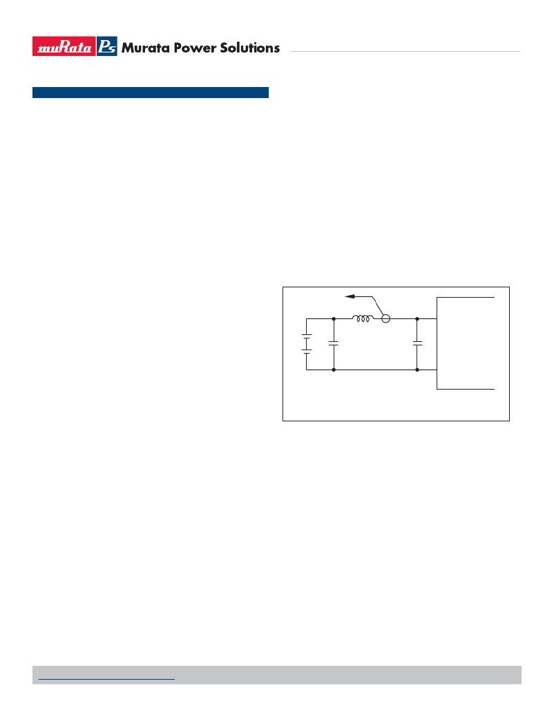
�I/O� Filtering,� Input� Ripple� Current� and� Output� Noise�
�All� models� in� this� converter� series� are� tested� and� speci?ed� for� input� re?ected�
�ripple� current� and� output� noise� using� designated� external� input/output� compo-�
�nents,� circuits� and� layout� as� shown� in� the� ?gures� below.� External� input� capaci-�
�tors� (C� IN� in� the� ?gure)� serve� primarily� as� energy� storage� elements,� minimizing�
�line� voltage� variations� caused� by� transient� IR� drops� in� the� input� conductors.�
�Users� should� select� input� capacitors� for� bulk� capacitance� (at� appropriate�
�frequencies),� low� ESR� and� high� RMS� ripple� current� ratings.� In� the� ?gure� below,�
�the� C� BUS� and� L� BUS� components� simulate� a� typical� DC� voltage� bus.� Your� speci?c�
�system� con?guration� may� require� additional� considerations.� Please� note� that� the�
�values� of� C� IN� ,� L� BUS� and� C� BUS� may� vary� according� to� the� speci?c� converter� model.�
�V� IN�
�until the rising input voltage exceeds and remains at the Start-UpThreshold�
�Voltage� (see� Speci?cations).� Once� operating,� converters� will� not� turn� off� until�
�the� input� voltage� drops� below� the� Under-Voltage� Shutdown� Limit.� Subsequent�
�restart� will� not� occur� until� the� input� voltage� rises� again� above� the� Start-Up�
�Threshold.� This� built-in� hysteresis� prevents� any� unstable� on/off� operation� at� a�
�single� input� voltage.�
�TO�
�OSCILLOSCOPE�
�+�
�–�
�+�
�C� BUS�
�L� BUS�
�CURRENT�
�PROBE�
�C� IN�
�+VIN�
�Users� should� be� aware� however� of� input� sources� near� the� Under-Voltage� Shut-�
�down� whose� voltage� decays� as� input� current� is� consumed� (such� as� capacitor�
�inputs),� the� converter� shuts� off� and� then� restarts� as� the� external� capacitor� re-�
�charges.� Such� situations� could� oscillate.� To� prevent� this,� make� sure� the� operating�
�input� voltage� is� well� above� the� UV� Shutdown� voltage� AT� ALL� TIMES.�
�Start-Up� Delay�
�Assuming� that� the� output� current� is� set� at� the� rated� maximum,� the� Vin� to� Vout� Start-�
�Up� Delay� (see� Speci?cations)� is� the� time� interval� between� the� point� when� the� rising�
�input� voltage� crosses� the� Start-Up� Threshold� and� the� fully� loaded� regulated� output�
�voltage� enters� and� remains� within� its� speci?ed� regulation� band.� Actual� measured�
�times� will� vary� with� input� source� impedance,� external� input� capacitance,� input� volt-�
�age� slew� rate� and� ?nal� value� of� the� input� voltage� as� it� appears� at� the� converter.�
�These� converters� include� a� soft� start� circuit� to� moderate� the� duty� cycle� of� the�
�PWM� controller� at� power� up,� thereby� limiting� the� input� inrush� current.�
�The� On/Off� Remote� Control� interval� from� inception� to� V� OUT� regulated� assumes� that�
�the� converter� already� has� its� input� voltage� stabilized� above� the� Start-Up� Threshold�
�before� the� On� command.� The� interval� is� measured� from� the� On� command� until� the�
�output� enters� 90%� of� its� speci?ed� regulation� band.� The� speci?cation� assumes� that�
�the� output� is� fully� loaded� at� maximum� rated� current.�
�Input� Source� Impedance�
�These� converters� will� operate� to� speci?cations� without� external� components,�
�assuming� that� the� source� voltage� has� very� low� impedance� and� reasonable� in-�
�put� voltage� regulation.� Since� real-world� voltage� sources� have� ?nite� impedance,�
�performance� is� improved� by� adding� external� ?lter� components.� Sometimes� only�
�a� small� ceramic� capacitor� is� suf?cient.� Since� it� is� dif?cult� to� totally� characterize�
�–�
�?VIN�
�C� IN� =� 33μF,� ESR� <� 200mΩ� @� 100kHz�
�C� BUS� =� 220μF,� 100V�
�L� BUS� =� 4.7μH�
�Figure� 2.� Measuring� Input� Ripple� Current�
�In� critical� applications,� output� ripple� and� noise� (also� referred� to� as� periodic� and�
�random� deviations� or� PARD)� may� be� reduced� by� adding� ?lter� elements� such� as�
�multiple� external� capacitors.� Be� sure� to� calculate� component� temperature� rise�
�from� re?ected� AC� current� dissipated� inside� capacitor� ESR.�
�Floating� Outputs�
�Since� these� are� isolated� DC/DC� converters,� their� outputs� are� “?oating”� with�
�respect� to� their� input.� The� essential� feature� of� such� isolation� is� ideal� ZERO�
�CURRENT� FLOW� between� input� and� output.� Real-world� converters� however� do�
�exhibit� tiny� leakage� currents� between� input� and� output� (see� Speci?cations).�
�These� leakages� consist� of� both� an� AC� stray� capacitance� coupling� component�
�and� a� DC� leakage� resistance.� When� using� the� isolation� feature,� do� not� allow�
�the� isolation� voltage� to� exceed� speci?cations.� Otherwise� the� converter� may�
�be� damaged.� Designers� will� normally� use� the� negative� output� (-Output)� as�
�the� ground� return� of� the� load� circuit.� You� can� however� use� the� positive� output�
�(+Output)� as� the� ground� return� to� effectively� reverse� the� output� polarity.�
�Minimum� Output� Loading� Requirements�
�These� converters� employ� a� synchronous� recti?er� design� topology.� All� models�
�regulate� within� speci?cation� and� are� stable� under� no� load� to� full� load� conditions.�
�all� applications,� some� experimentation� may� be� needed.� Note� that� external� input�
�capacitors� must� accept� high� speed� switching� currents.�
�www.murata-ps.com/support�
�MDC_HPQ-12/25-D48� Series.B07� Page� 12� of� 16�
�相关PDF资料 |
PDF描述 |
|---|---|
| MM74HC245AMTC | IC TRANSCVR 3-ST 8BIT 20TSSOP |
| 74LVC16240ADGG,512 | IC INVERTER QUAD 4-INPUT 48TSSOP |
| N74F804N,602 | IC HEX 2-IN NAND DRVR 20-DIP |
| N74F1804N,602 | IC GATE NAND HEX 2INPUT 20DIP |
| N74F1804D,602 | IC GATE NAND HEX 2INPUT 20SOICW |
相关代理商/技术参数 |
参数描述 |
|---|---|
| HPQ1225D48NL1C | 制造商:Murata Power Solutions 功能描述: |
| HPQ-12-D48_11 | 制造商:MURATA 制造商全称:Murata Manufacturing Co., Ltd. 功能描述:Isolated 300-Watt Quarter Brick DC/DC Converters |
| HPQ-12W | 制造商:MINI 制造商全称:Mini-Circuits 功能描述:POWER SPLITTERS/COMBINERS |
| HPQ-15 | 制造商:MINI 制造商全称:Mini-Circuits 功能描述:POWER SPLITTERS/COMBINERS |
| HPQ-15W | 制造商:MINI 制造商全称:Mini-Circuits 功能描述:POWER SPLITTERS/COMBINERS |
发布紧急采购,3分钟左右您将得到回复。