参数资料
| 型号: | HS201DR-CC2425W3U |
| 厂商: | Crydom Co. |
| 文件页数: | 4/16页 |
| 文件大小: | 0K |
| 描述: | RELAY SSR SPST 35A W/HEATSINK ZC |
| 其它有关文件: | Declaration of Conformity |
| 标准包装: | 10 |
| 系列: | HS |
| 电路: | SPST-NO(1 Form A) |
| 输出类型: | AC,过零 |
| 负载电流: | 35A |
| 输入电压: | 4 ~ 32VDC |
| 电压 - 负载: | 24 ~ 280 V |
| 安装类型: | DIN 轨道 |
| 端接类型: | 螺丝端子 |
| 封装/外壳: | Hockey Puck with Heat Sink |
| 包装: | 散装 |
| 继电器类型: | 继电器 |
�� �
�
�Heat� Sink� Selection�
�Why� Heat� Sinks� are� required� for� Reliable� Solid�
�State� Relay� operation�
�Heat� Sinks� are� required� to� insure� the� proper� operation� and� long� term�
�reliability� of� Solid� State� Relays� because� they� provide� a� means� to� dissipate�
�the� power� that� is� normally� developed� internally� in� the� SSR� into� the�
�A�
�B�
�C�
�D�
�The� selected� SSR� with� specified� thermal� impedance� (R� Θ� ssr� ),� forward�
�voltage� drop� (V� f� ),� and� maximum� allowed� internal� operating� temperature�
�(T� j� ).�
�The� thermal� interface� material� placed� between� the� SSR� and� the� Heat�
�Sink� and� its� specified� thermal� impedance� (R� Θ� tp� ).�
�The� calculated� minimum� Heat� Sink� thermal� impedance� rating� (R� Θ� hs� )�
�required� for� proper� SSR� operation.�
�The� operating� environment’s� max� ambient� air� temperature� in� °C� (T� A� ).�
�surrounding� ambient� air� and� maintain� a� safe� operating� temperature.�
�A�
�B�
�C�
�D�
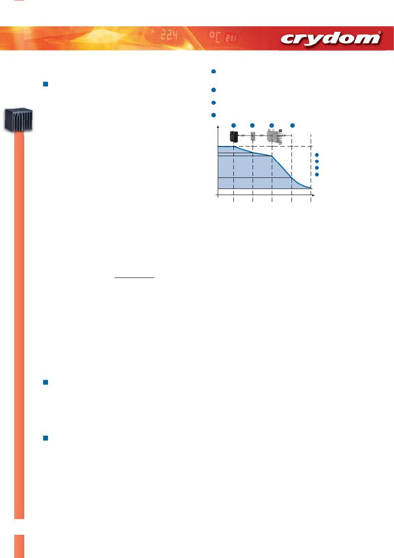
�All� SSRs� in� their� conduction� state� create� thermal� energy� in� the� output�
�semiconductor� at� the� rate� of� approximately� 1� to� 1.5� watts� per� ampere� of� load�
�current� for� AC� output� SSRs,� and� 0.2� to� 1.5� watts� per� ampere� of� load� current�
�for� DC� output� SSRs� depending� upon� their� design.� This� power� dissipation�
�raises� the� Solid� State� Relay’s� operating� temperature� above� the� surrounding�
�ambient.�
�Solid� State� Relays� can� operate� reliably� without� heat� sinks� up� to�
�T� J�
�T� B�
�T� HS2�
�T� HS1�
�A�
�B�
�C�
�D�
�Panel� Mount� SSR�
�Thermal� Interface� Material�
�Heat� Sink�
�Ambient� Air�
�approximately� 5� amps� of� load� current� depending� upon� model,� duty� cycle�
�and� ambient� temperature.� Free� air� ratings� of� traditional� panel� mount� SSRs�
�may� be� as� high� as� 8� to� 10� amps,� but� this� rating� relies� on� the� SSRs� exposed�
�metal� base� plate� acting� as� a� heat� sink,� meaning� that� it� must� be� exposed� to�
�ambient� air.�
�Heat� Sinks� are� made� of� high� thermal� conductive� material� such� as�
�aluminum.� Not� only� is� aluminum’s� thermal� conductivity� high,� its� cost� is�
�relatively� low.� Although� other� materials� such� as� steel� may� provide� a� limited�
�measure� of� heat� sinking,� thermal� conductivity� of� these� materials� are�
�relatively� low� compared� to� aluminum� and� therefore� far� less� effective� as� a�
�Heat� Sink� .� Coatings� also� tend� to� diminish� the� thermal� dissipation�
�T� A�
�R� θSSR� R� θTP� R� θHS� T� A�
�Solid� State� Relay� -� Heat� Sink� Assembly� Thermal� Model�
�To� determine� the� minimum� Heat� Sink� rating� (R� Θ� hs� )� required� for� a� particular�
�application,� the� SSRs� internal� power� dissipation� must� first� be� calculated.�
�The� power� developed� in� the� SSR� will� be� the� product� of� the� actual� load�
�current� in� amps� times� the� SSRs� specified� on� state� voltage� drop� at� that�
�current� (� P� d� =� I� f� x� V� f� ).� Note:� Manufacturers� generally� specify� 'maximum�
�forward� voltage� drop'� in� their� data� sheets.� Typical� voltage� drops� are� often�
�much� lower.�
�effectiveness� of� most� materials� and� except� anodizing,� should� be� avoided.�
�For� this� example,� assume� that� a� 25� amp� AC� output� SSR� is� selected� to� switch�
�Heat� Sink� performance� is� rated� by� thermal� impedance,� measured� in� °C� per�
�watt� (°C/W)� (thermal� impedance� is� the� inverse� of� thermal� conductivity).�
�Thermal� impedance� represents� the� resistance� to� the� transfer� of� thermal�
�energy,� therefore� lower� numerical� thermal� impedance� ratings� mean� more�
�efficient� heat� transfer.�
�Thermal� Impedance� ratings� of� Heat� Sinks� are� based� upon� natural�
�convection� air� flow.� To� achieve� this� performance,� the� Heat� Sink� must� be�
�oriented� such� that� air� flow� over� its� finned� surface� is� maximized.� Generally�
�an� AC� load� current� of� 18� amps� with� forward� voltage� drop� specified� to� be� 1.25�
�volts.� Therefore� the� power� generated� in� the� SSR� is� 18� amps� times� 1.25� volts�
�=� 22.5� watts.�
�Next,� determine� the� Solid� State� Relay’s� specified� thermal� impedance� and�
�allowed� maximum� internal� temperature� (if� the� max� internal� temperature� is�
�not� specified� by� the� manufacturer,� assume� 125� °C� as� this� is� a� common� value�
�for� many� AC� power� semiconductors).� For� this� example,� assume� R� Θ� ssr� of� 0.3�
�°C/W� and� T� j� of� 125� °C.�
�this� means� the� fins� should� be� orientated� vertically.�
�The� next� step� is� to� determine� the� maximum� operating� ambient� temperature�
�Significant� improvement� in� Heat� Sink� performance� can� be� achieved� by�
�providing� forced� air� flow� over� the� Heat� Sink’s� surface� area.� Fans� delivering�
�relatively� small� volumes� of� air� can� reduce� the� Heat� Sink’s� thermal�
�impedance� substantially,� thereby� improving� its� efficiency� and� consequently�
�the� SSRs� reliability.�
�Selecting� a� Heat� Sink� for� a� given� Solid� State�
�Relay� application�
�Crydom� offers� technical� assistance� selecting� a� heat� sink� for� any� given� SSR�
�application� through� its� Applications� Engineering� Department� and� on� its� web�
�site.� Available� “White� Papers”� and� a� selection� “tool”� to� calculate� a� heat� sink�
�rating� based� upon� load� current� and� ambient� temperature� are� available� at�
�www.crydom.com� .�
�How� to� calculate� and� select� a� Heat� Sink� for� a�
�given� Solid� State� Relay� application�
�The� basic� structure� of� a� Solid� State� Relay� includes� an� internal� power�
�semiconductor� mounted� to� an� electrical� insulator� which� in� turn� is� mounted�
�to� the� Solid� State� Relay’s� base� plate.� To� form� an� assembly,� the� SSR� with� an�
�accompanying� thermal� interface� material� placed� on� its� base� plate� is� then�
�torque� mounted� to� the� Heat� Sink� .�
�The� thermal� model� representing� the� above� configuration� includes� the�
�following� elements:�
�(T� A� )� in� °C� that� the� SSR� will� be� expected� to� operate� in� its� application.� The�
�ambient� value� should� be� the� ambient� air� temperature� of� the� local�
�environment� such� as� the� interior� of� a� control� cabinet� where� the� SSR� and�
�Heat� Sink� are� to� be� mounted.� In� this� example,� assume� T� A� of� 55� °C.�
�Finally,� the� thermal� impedance� of� the� interface� material� (R� Θ� tp� )� must� be�
�determined.� These� materials� will� vary� from� 0.02� to� 0.1� °C� per� watt�
�depending� upon� the� type� and� thickness� selected.� For� this� example,� assume�
�that� the� thermal� impedance� of� the� selected� interface� material� R� Θ� tp� is� 0.05�
�°C/W.�
�The� first� calculation� is� to� determine� the� temperature� span� (� ?� t)� that� the�
�SSRs� power� must� be� dissipated� into� in� order� to� maintain� its� proper�
�operation.� This� will� be� the� difference� between� the� SSRs� maximum� allowed�
�internal� temperature� and� the� local� ambient� temperature.� ?� t� =� T� j� max� –� T� A� .�
�In� this� example� the� result� would� be:� ?� t� =� 125� –� 55� =� 70� °C.�
�The� maximum� allowed� temperature� rise� noted� above,� ?� t,� must� then� be� less�
�than� or� equal� to� the� combined� sum� of� temperature� rises� across� the� three�
�impedances� times� the� power� being� developed� in� the� SSR.� ?� t� <� (R� Θ� ssr� +� R� Θ� tp�
�+� R� Θ� hs� )� times� P� d� .� For� this� example� it� would� be� 70� <� (0.3� +� 0.05� +� R� Θ� hs� )� x� 22.5.�
�Therefore� the� Heat� Sink� thermal� impedance� is� R� Θ� hs� <� (� ?� t� /P� d� )� –� (R� Θ� ssr� +� R� Θ� tp� )�
�or� 70/22.5� –� 0.35,� equaling� 2.76� °C/W.�
�Therefore� in� this� example,� a� 2.75� °C/W� or� larger� (lower� numerical� value)�
�Heat� Sink� should� be� used� with� the� Solid� State� Relay� in� the� application� as�
�described� above.�
�4�
�Questions?� Call� or� e-mail�
�Americas� +1� (877)� 502� 5500� sales@crydom.com�
�Europe� +44� (0)� 1202� 606030� sales-europe@crydom.com�
�相关PDF资料 |
PDF描述 |
|---|---|
| 6-1437644-2 | CONN TERM BLK TAB SINGLE 45 DEG |
| 3-1393816-2 | RELAY GEN PURPOSE 4PDT 2A 110V |
| 6-1437644-4 | CONN TERM BLK TAB SINGLE 45 DEG |
| 6-1437644-6 | CONN TAB QC RT ANG TIN .250 |
| CMRA4865 | RELAY SSR SCR 65A 530V PNL MNT |
相关代理商/技术参数 |
参数描述 |
|---|---|
| HS201DR-D2450 | 功能描述:散热片 35A/240V DC Input ZC SSR Mounted Heatsink RoHS:否 制造商:Ampro By ADLINK 产品:Heat Sink Accessories 安装风格:Through Hole 散热片材料: 散热片样式: 热阻: 长度: 宽度: 高度: 设计目的:Express-HRR |
| HS201DR-HD6050 | 功能描述:散热片 35A/660V DC Input ZC SSR Mounted Heatsink RoHS:否 制造商:Ampro By ADLINK 产品:Heat Sink Accessories 安装风格:Through Hole 散热片材料: 散热片样式: 热阻: 长度: 宽度: 高度: 设计目的:Express-HRR |
| HS-201HSRH | 制造商:INTERSIL 制造商全称:Intersil Corporation 功能描述:Radiation Hardened High Speed, Quad SPST, CMOS Analog Switch |
| HS-201HSRH_06 | 制造商:INTERSIL 制造商全称:Intersil Corporation 功能描述:Radiation Hardened High Speed, Quad SPST, CMOS Analog Switch |
| HS-201HSRH_13 | 制造商:INTERSIL 制造商全称:Intersil Corporation 功能描述:Radiation Hardened High Speed, Quad SPST, CMOS Analog Switch |
发布紧急采购,3分钟左右您将得到回复。