- 您现在的位置:买卖IC网 > PDF目录370725 > HV3-2405E-9 (INTERSIL CORP) World-WideSingle Chip Power Supply PDF资料下载
参数资料
| 型号: | HV3-2405E-9 |
| 厂商: | INTERSIL CORP |
| 元件分类: | 基准电压源/电流源 |
| 英文描述: | World-WideSingle Chip Power Supply |
| 中文描述: | 5 V-24 V ADJUSTABLE POSITIVE REGULATOR, PDIP8 |
| 封装: | PLASTIC, DIP-8 |
| 文件页数: | 4/14页 |
| 文件大小: | 573K |
| 代理商: | HV3-2405E-9 |
5-18
HV-2405E
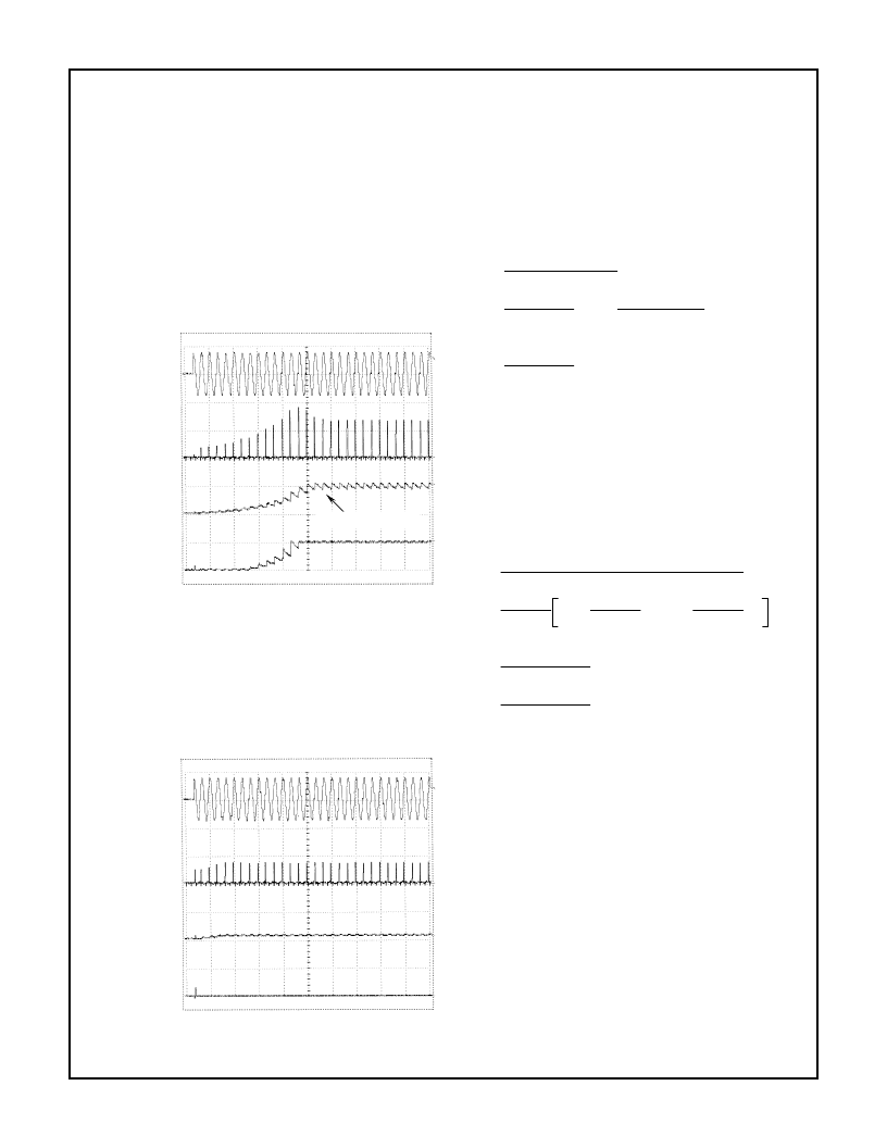
C2 is greater than 10V. The circuits operation is illustrated in
Figure 2 and Figure 3. In Figure 2 the initial current pulse is
approximately 400mA when V
C2
= 0V and gradually
increases to approximately 1.8A when C2 = 10V. Also notice
that after the 17th line cycle the input current is approxi-
mately 1.4A. At this point C2 is fully charged. The input cur-
rent required to maintain the voltage on C2 is less than the
current to charge it and the circuit has reached steady state
operation. Since the steady state current is less than the
input current limit, the circuit in the shaded area is off and no
longer has any effect.
FIGURE 2. START UP OPERATION
Under short circuit operation the maximum voltage on pin 2
is less than 10V and the input current limiting circuit is
invoked. Figure 3 shows that under output short circuit con-
ditions, the input current is limited to about 800mA. The
effects on the output current when the input current limiting
circuit is invoked is illustrated in Figure 6.
FIGURE 3. SHORT CIRCUIT OPERATION
V
IN
= 264Vrms
(500V/DIV)
INPUT CURRENT
(1A/DIV)
I
P
≈
0.8A
V
(10V/DIV)
V
OUT
(5V/DIV)
C2 FULLY CHARGED
TIME (50ms/DIV)
OFFLINE WORLD-SIDE SUPPLY
I
OUT
= 50mA
V
IN
= 264Vrms
(500V/DIV)
INPUT CURRENT
(1A/DIV)
I
P
≈
0.8A
V
C2
(10V/DIV)
V
OUT
(5V/DIV)
OFFLINE WORLD-WIDE SUPPLY
TIME (50ms/DIV)
Design Equations for Input Current Limiting
Initial Start-Up
Assume:
R4 = 5.6k
, R5 = 3.3k
, R6 = 5.6k
, V
BE
= 0.54V, I
TRIG
=
60
μ
A, V
Pin 8
- V
Pin 2
= 3.5V at low inputs currents. V
IN1
=
Voltage on AC high when input current limit circuit is invoked
(V
C2
= 0V)
V
IN1
- V
Pin 8
- V
Pin 2
R1
R2 + R3
(V
BE
+
R3
R4 + R5 + R6
V
IN1
= 57.41 (0.54 + 3.437k
x 60
μ
A) = 42.84V
42.84 - 3.5
= 393mA
100
V
C2
= 0V, R1 = 100
, R2 = 220k
, R3 = 3.9k
,
Equation 1 through Equation 4, for the given assumptions,
predict that the initial input current will be limited to 393mA.
The following equations can be used to predict the maximum
input current during start-up.
Assume:
V
C2
> 10V, R1 = 100
, R2 = 220k
, R3 = 3.9k
,
R4 = 5.6k
, R5 = 5.6k
, R6 = 3.3k
, V
BE
= 0.54V, I
TRIG
=
60
μ
A, V
Z
= 5.1V, V
Pin 8
- V
Pin 2
= 6V at high inputs currents,
V
Pin 2
- V
Pin 6
, V
IN2
= Voltage on AC high when input current
circuit is invoked (V
C2
> 10V).
V
IN2
- V
OUT
- (V
Pin 8
- V
Pin 2
) - (V
Pin 2
- V
Pin 6
)
R1
R2 + R3
(V
BE
+
R3
R4 + R5
V
IN2
= 57.41 [0.54 + (2.076k
x 60
μ
A) + (0.6292 x 5.1)]
222 - V
OUT
-6 -6
= 2.05A at V
OUT
= 5V
100
222 - V
OUT
-6 -6
= 1.86A at V
OUT
= 24V
100
Equation 5 through Equation 9 predict the maximum input
current will be limited to less than 2.05A. In practice at 5V
operation the current is less than predicted due to the low
bias current through Z2.
Setting The Output Voltage
The circuit shown in Figure 1 provides a regulated 5V to 24V
DC and is set by adjusting the value of Z1. The output volt-
age of the HV-2405E (pin 6) is set by feedback to the sense
pin (pin 5). The output will rise to the voltage necessary to
keep the sense pin at 5V. The output voltage is equal to the
Zener voltage (V
Z1
) plus the 5V on the sense pin. For a 5V
output, pin 5 and pin 6 would be shorted together. The out-
put voltage has the accuracy and tolerance of both the Zener
diode and the band-gap of the HV-2405E (see Figure 16).
The maximum output voltage is limited by Z
B2
to
≈
34V
DC
.
Z
B2
protects the output by ensuring that an overvoltage con-
dition does not exist. Note: the output voltage can also be set
by placing a resistor (1/4W) between pin 5 and pin 6. If a
resistor is placed between pin 5 and pin 6 an additional 1V
per k
(
±
10%) is added to the 5V output.
I
IN(min)
=
(EQ 1)
V
IN1
=
R4 (R5 + R6)
x I
TRIG
)
(EQ. 2)
(EQ. 3)
I
IN(min)
=
(EQ. 4)
I
IN(max)
=
(EQ. 5)
V
IN2
=
R4 R5
x I
TRIG
+
R4
V
Z2
(EQ. 6)
R4 + R5
(EQ. 7)
I
IN(max)
=
(EQ. 8)
I
IN(max)
=
(EQ. 9)
Application Information
(Continued)
相关PDF资料 |
PDF描述 |
|---|---|
| HV341C | Interface IC |
| HV341MC | Interface IC |
| HV341MWG | Interface IC |
| HV341P | Interface IC |
| HV341WG | Interface IC |
相关代理商/技术参数 |
参数描述 |
|---|---|
| HV3-2405E-9 DIE | 制造商:Harris Corporation 功能描述: |
| HV33 | 制造商:WELWYN 制造商全称:Welwyn Components Limited 功能描述:High Voltage Thick film Resistors |
| HV3304DJ | 制造商:未知厂家 制造商全称:未知厂家 功能描述:Interface IC |
| HV3304PJ | 制造商:未知厂家 制造商全称:未知厂家 功能描述:Interface IC |
| HV3304X | 制造商:未知厂家 制造商全称:未知厂家 功能描述:Interface IC |
发布紧急采购,3分钟左右您将得到回复。