- 您现在的位置:买卖IC网 > PDF目录383091 > ICM7216A (Intersil Corporation) 8-Digit, Multi-Function, Frequency Counters/Timers PDF资料下载
参数资料
| 型号: | ICM7216A |
| 厂商: | Intersil Corporation |
| 元件分类: | 通用总线功能 |
| 英文描述: | 8-Digit, Multi-Function, Frequency Counters/Timers |
| 中文描述: | 8位数字,多功能,频率计数器/定时器 |
| 文件页数: | 11/17页 |
| 文件大小: | 141K |
| 代理商: | ICM7216A |
9-20
Time Interval Measurement
When in the
time interval
mode and measuring a single
event, the lCM7216A and lCM7216B must first be “primed”
prior to measuring the event of interest. This is done by first
generating a negative going edge on Channel A followed by a
negative going edge on Channel B to start the “measurement
interval”. The inputs are then primed ready for the measure-
ment. Positive going edges on A and B, before or after the
priming, will be needed to restore the original condition.
Priming can be easily accomplished using the circuit in
Figure 13.
Following the priming procedure (when in single event or 1
cycle range) the device is ready to measure one (only)
event.
When timing repetitive signals, it is not necessary to “prime”
the lCM7216A and lCM7216B as the first alternating signal
states automatically prime the device. See Figure 1.
During any time interval measurement cycle, the ICM7216A
and lCM7216B require 200ms following B going low to
update all internal logic. A new measurement cycle will not
take place until completion of this internal update time.
Oscillator Considerations
The oscillator is a high gain CMOS inverter. An external
resistor of 10M
to 22M
should be connected between the
OSCillator INPUT and OUTPUT to provide biasing. The
oscillator is designed to work with a parallel resonant 10MHz
quartz crystal with a static capacitance of 22pF and a series
resistance of less than 35
.
For a specific crystal and load capacitance, the required g
M
can be calculated as follows:
C
O
= Crystal Static Capacitance
R
S
= Crystal Series Resistance
C
IN
= Input Capacitance
C
OUT
= Output Capacitance
ω
= 2
π
f
The required g
M
should not exceed 50% of the g
M
specified
for the lCM7216 to insure reliable startup. The OSCillator
INPUT and OUTPUT pins each contribute about 5pF to C
IN
and C
OUT
. For maximum stability of frequency, C
IN
and
C
OUT
should be approximately twice the specified crystal
static capacitance.
In cases where non decade prescalers are used it may be
desirable to use a crystal which is neither 10MHz or 1MHz.
In that case both the multiplex rate and time between mea-
surements will be different. The multiplex rate is
for 10MHz mode and
for
the 1MHz mode. The time between measurements is
in the 10MHz mode and
in the 1MHz mode.
The crystal and oscillator components should be located as
close to the chip as practical to minimize pickup from other
signals. Coupling from the EXTERNAL OSClLLATOR INPUT
to the OSClLLATOR OUTPUT or INPUT can cause undesir-
able shifts in oscillator frequency.
Display Considerations
The display is multiplexed at a 500Hz rate with a digit time of
244
μ
s. An interdigit blanking time of 6
μ
s is used to prevent
display ghosting (faint display of data from previous digit
superimposed on the next digit). Leading zero blanking is
provided, which blanks the left hand zeroes after decimal
point or any non zero digits. Digits to the right of the decimal
point are always displayed. The leading zero blanking will be
disabled when the Main Counter overflows.
The lCM7216A is designed to drive common anode LED
displays at peak current of 25mA/segment, using displays
with V
F
= 1.8V at 25mA. The average DC current will be over
3mA under these conditions. The lCM7216B and lCM7216D
are designed to drive common cathode displays at peak cur-
rent of 15mA/segment using displays with V
F
= 1.8V at
15mA. Resistors can be added in series with the segment
drivers to limit the display current in very efficient displays, if
required. The Typical Performance Curves show the digit
and segment currents as a function of output voltage.
To get additional brightness out of the displays, V
DD
may be
increased up to 6.0V. However, care should be taken to see
that maximum power and current ratings are not exceeded.
The segment and digit outputs in lCM7216s are not directly
compatible with either TTL or CMOS logic when driving
LEDs. Therefore, level shifting with discrete transistors may
be required to use these outputs as logic signals.
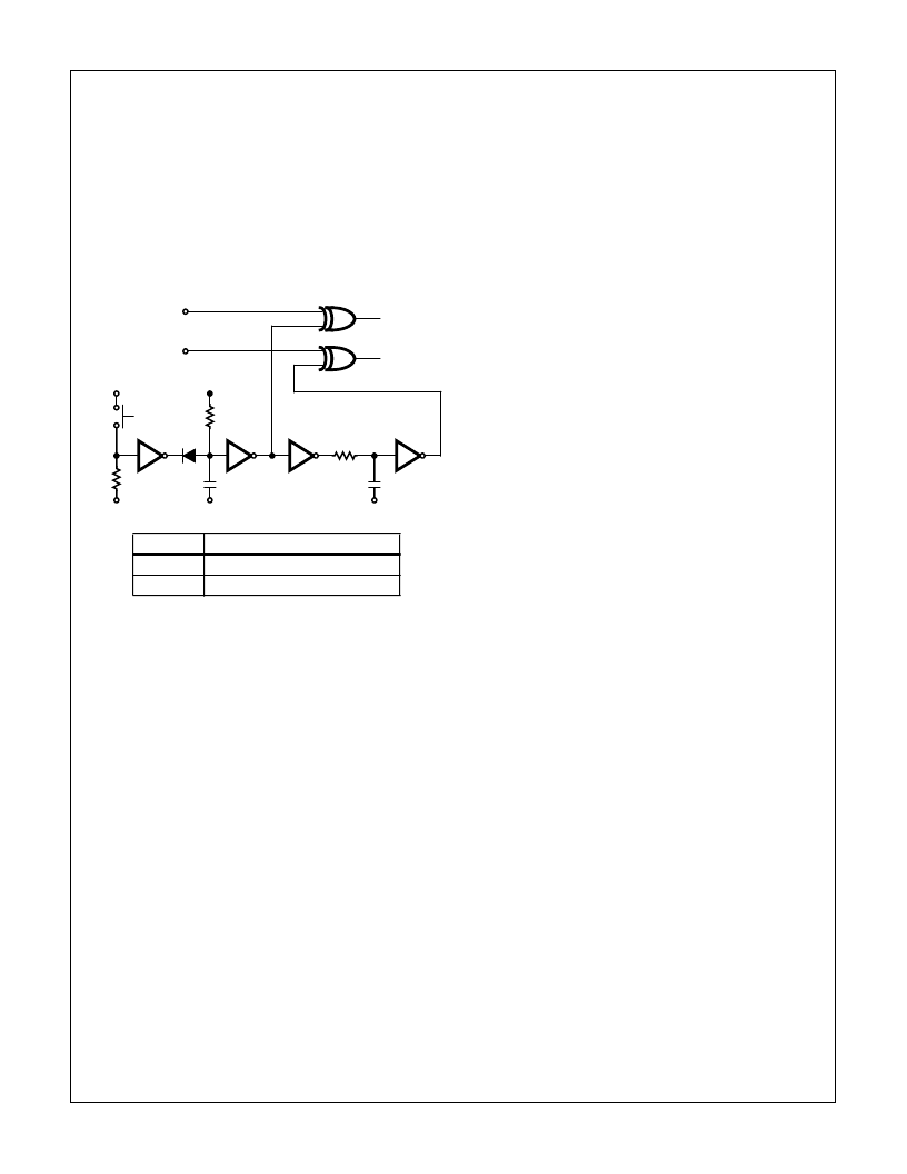
SIGNAL A
SIGNAL B
INPUT A
INPUT B
V
DD
N.O.
100K
1N914
V
DD
150K
1
0.1
μ
F
10K
10nF
1
1
1
2
2
V
SS
V
SS
V
SS
PRIME
FIGURE 13. PRIMING CIRCUIT, SIGNALS A AND B BOTH HIGH
OR LOW
DEVICE
TYPE
1
CD4049B Inverting Buffer
2
CD4070B Exclusive - OR
g
M
ω
2
C
IN
C
OUT
R
S
1
C
O
C
L
--------
+
2
=
where C
L
C
C
IN
OUT
------------+
=
f
MUX
f
10
4
×
2
------------------
=
f
MUX
f
10
3
×
2
------------------
=
------------------
6
OSC
------------------
5
OSC
ICM7216A, ICM7216B, ICM7216D
相关PDF资料 |
PDF描述 |
|---|---|
| ICM7216BlPl | 8-Digit, Multi-Function, Frequency Counters/Timers |
| ICM7216D | 8-Digit, Multi-Function, Frequency Counters/Timers |
| ICM7216DlPl | 8-Digit, Multi-Function, Frequency Counters/Timers |
| ICM7216AlJl | Circular Connector; No. of Contacts:79; Series:MS27496; Body Material:Aluminum; Connecting Termination:Crimp; Connector Shell Size:21; Circular Contact Gender:Pin; Circular Shell Style:Box Mount Receptacle; Insert Arrangement:21-35 RoHS Compliant: No |
| ICM7217IJI | 4 Digit (LED) Presettable Up/Down Counter |
相关代理商/技术参数 |
参数描述 |
|---|---|
| ICM7216AIJI | 制造商:Intersil Corporation 功能描述:IC UNIVERSAL COUNTER 7216 DIP28 |
| ICM7216AIJI WAF | 制造商:Intersil Corporation 功能描述: |
| ICM7216ALJL | 制造商:INTERSIL 制造商全称:Intersil Corporation 功能描述:8-Digit, Multi-Function, Frequency Counters/Timers |
| ICM7216B | 制造商:INTERSIL 制造商全称:Intersil Corporation 功能描述:8-Digit, Multi-Function, Frequency Counters/Timers |
| ICM7216B_04 | 制造商:INTERSIL 制造商全称:Intersil Corporation 功能描述:8-Digit, Multi-Function, Frequency Counters/Timers |
发布紧急采购,3分钟左右您将得到回复。