- 您现在的位置:买卖IC网 > PDF目录383091 > ICM7216D (Intersil Corporation) 8-Digit, Multi-Function, Frequency Counters/Timers PDF资料下载
参数资料
| 型号: | ICM7216D |
| 厂商: | Intersil Corporation |
| 元件分类: | 通用总线功能 |
| 英文描述: | 8-Digit, Multi-Function, Frequency Counters/Timers |
| 中文描述: | 8位数字,多功能,频率计数器/定时器 |
| 文件页数: | 8/17页 |
| 文件大小: | 141K |
| 代理商: | ICM7216D |
9-17
Description
INPUTS A and B
INPUTS A and B are digital inputs with a typical switching
threshold of 2V at V
DD
= 5V. For optimum performance the
peak-to-peak input signal should be at least 50% of the
supply voltage and centered about the switching voltage.
When these inputs are being driven from TTL logic, it is
desirable to use a pullup resistor. The circuit counts high to
low transitions at both inputs. (INPUT B is available only on
lCM7216A and lCM7216B).
Note that the amplitude of the input should not exceed the
device supply (above the V
DD
and below the V
SS
) by more
than 0.3V, otherwise the device may be damaged.
Multiplexed Inputs
The FUNCTION, RANGE, CONTROL and EXTERNAL
DECIMAL POINT inputs are time multiplexed to select the
function desired. This is achieved by connecting the appro-
priate Digit driver output to the inputs. The function, range
and control inputs must be stable during the last half of each
digit output, (typically 125
μ
s). The multiplexed inputs are
active high for the common anode lCM7216A and active low
for the common cathode lCM7216B and lCM7216D.
Noise on the multiplex inputs can cause improper operation.
This is particularly true when the
unit counter
mode of
operation is selected, since changes in voltage on the digit
drivers can be capacitively coupled through the LED diodes
to the multiplex inputs. For maximum noise immunity, a 10k
resistor should be placed in series with the multiplexed
inputs as shown in the application circuits.
Table 1 shows the functions selected by each digit for these
inputs.
9.
Function Input
The six functions that can be selected are:
Frequency,
Period, Time Interval, Unit Counter, Frequency Ratio
and
Oscillator Frequency.
This input is available on the
lCM7216A and lCM7216B only.
The implementation of different functions is done by routing
the different signals to two counters, called “Main Counter”
and “Reference Counter”. A simplified block diagram of the
device for functions realization is shown in Figure 11. Table 2
shows which signals will be routed to each counter in
different cases. The output of the Main Counter is the
information which goes to the display. The Reference
Counter divides its input by 1, 10, 100 and 1000. One of
these outputs will be selected through the range selector
and drive the enable input of the Main Counter. This means
that the Reference Counter, along with its associated blocks,
directs the Main Counter to begin counting and determines
the length of the counting period. Note that Figure 11 does
not show the complete functional diagram (See the
Functional Block Diagram). After the end of each counting
period, the output of the Main Counter will be latched and
displayed, then the counter will be reset and a new
measurement cycle will begin. Any change in the
FUNCTION INPUT will stop the present measurement
without updating the display and then initiate a new
measurement. This prevents an erroneous first reading after
the FUNCTION INPUT is changed. In all cases, the 1-0
transitions are counted or timed.
TABLE 1. MULTIPLEXED INPUT FUNCTIONS
FUNCTION
DIGIT
FUNCTION INPUT (Pin
3, lCM7216A and B
Only)
Frequency
D1
Period
D8
Frequency Ratio
D2
Time Interval
D5
Unit Counter
D4
Oscillator Frequency
D3
RANGE INPUT, Pin 14
0.01s/1 Cycle
D1
0.1s/10 Cycles
D2
1s/100 Cycles
D3
10s/1K Cycles
D4
CONTROL INPUT,
Pin 1
Display Off
D4 and
Hold
Display Test
D8
1MHz Select
D2
External Oscillator Enable
D1
External Decimal Point
Enable
D3
External DP INPUT (Pin
13, ICM7216D Only)
Decimal point is output for same digit
that is connected to this input.
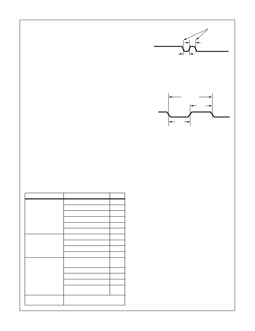
INPUT A
4.5V
0.5V
50ns MIN
t
r
= t
f
= 10ns
COUNTED
TRANSITIONS
50ns MIN
FIGURE 9. WAVEFORM FOR GUARANTEED MINIMUM f
A
(MAX)
FUNCTION = FREQUENCY, FREQUENCY RATIO,
UNIT COUNTER
INPUT A OR
INPUT B
4.5V
0.5V
MEASURED
INTERVAL
250ns
MIN
t
r
= t
f
= 10s
250ns
MIN
FIGURE 10. WAVEFORM FOR GUARANTEED MINIMUM f
B
(MAX)
AND f
A
(MAX) FOR FUNCTION = PERIOD AND
TIME INTERVAL
ICM7216A, ICM7216B, ICM7216D
相关PDF资料 |
PDF描述 |
|---|---|
| ICM7216DlPl | 8-Digit, Multi-Function, Frequency Counters/Timers |
| ICM7216AlJl | Circular Connector; No. of Contacts:79; Series:MS27496; Body Material:Aluminum; Connecting Termination:Crimp; Connector Shell Size:21; Circular Contact Gender:Pin; Circular Shell Style:Box Mount Receptacle; Insert Arrangement:21-35 RoHS Compliant: No |
| ICM7217IJI | 4 Digit (LED) Presettable Up/Down Counter |
| ICM7217IPI | 4 Digit (LED) Presettable Up/Down Counter |
| ICM7217AIPI | 4 Digit (LED) Presettable Up/Down Counter |
相关代理商/技术参数 |
参数描述 |
|---|---|
| ICM7216DIPI | 功能描述:IC COUNTER/TIMER FREQ 8DIG 28DIP RoHS:否 类别:未定义的类别 >> 其它 系列:* 标准包装:1 系列:* 其它名称:MS305720A |
| ICM7216DIPI WAF | 制造商:Intersil Corporation 功能描述: |
| ICM7216DLPL | 制造商:INTERSIL 制造商全称:Intersil Corporation 功能描述:8-Digit, Multi-Function, Frequency Counters/Timers |
| ICM7217 | 制造商:MAXIM 制造商全称:Maxim Integrated Products 功能描述:4 Digit (LED) Presettable Up/Down Counter |
| ICM7217_01 | 制造商:INTERSIL 制造商全称:Intersil Corporation 功能描述:4-Digit LED Display, Programmable Up/Down Counter |
发布紧急采购,3分钟左右您将得到回复。