- 您现在的位置:买卖IC网 > PDF目录224008 > IDT74FST3126Q8 (INTEGRATED DEVICE TECHNOLOGY INC) CBT/FST/QS/5C/B SERIES, 4-BIT DRIVER, TRUE OUTPUT, PDSO16 PDF资料下载
参数资料
| 型号: | IDT74FST3126Q8 |
| 厂商: | INTEGRATED DEVICE TECHNOLOGY INC |
| 元件分类: | 总线收发器 |
| 英文描述: | CBT/FST/QS/5C/B SERIES, 4-BIT DRIVER, TRUE OUTPUT, PDSO16 |
| 封装: | QSOP-16 |
| 文件页数: | 2/5页 |
| 文件大小: | 77K |
| 代理商: | IDT74FST3126Q8 |
2
COMMERCIALTEMPERATURERANGE
IDT74FST3126
QUADRUPLE BUS SWITCH WITH INDIVIDUAL POSITIVE ENABLES
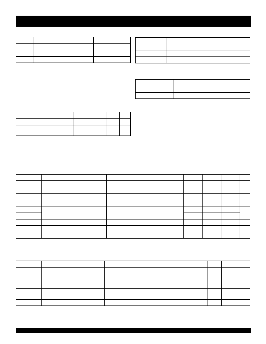
ABSOLUTE MAXIMUM RATINGS(1)
Symbol
Rating
Max.
Unit
VTERM(2)
Terminal Voltage with Respect to GND
–0.5 to +7
V
TSTG
Storage Temperature
–65 to +150
°C
IOUT
Maximum Continuous Channel Current
128
mA
FST LINK
NOTES:
1. Stresses greater than those listed under ABSOLUTE MAXIMUM
RATINGS may cause permanent damage to the device. This is a
stress rating only and functional operation of the device at these or
any other conditions above those indicated in the operational sections
of this specification is not implied. Exposure to absolute maximum
rating conditions for extended periods may affect reliability.
2. Vcc, Control, and Switch terminals.
PIN DESCRIPTION
Pin Names
I/O
Description
xOE
I
Bus Switch Enable (Active HIGH)
xA
I/O
Bus A
xB
I/O
Bus B
FUNCTION TABLE (1)
OE
A, B
Description
L
Hi-Z
Disconnect
H
A = B
Connect
NOTE:
1. H = HIGH
L = LOW
CAPACITANCE (1)
Symbol
Parameter
Conditions(2)
Typ.
Unit
CIN
Control Input Capacitance
8
pF
CI/O
Switch Input/Output
Capacitance
Switch Off
13
pF
NOTES:
1. Capacitance is characterized but not tested.
2. TA = 25°C, f = 1MHz, VIN = 0V, VOUT = 0V
DC ELECTRICAL CHARACTERISTICS OVER OPERATING RANGE
Following Conditions Apply Unless Otherwise Specified:
Operating Conditions: TA = -40°C to +85°C, VCC = 5.0V ±10%
Symbol
Parameter
Test Conditions
Min.
Typ.(1)
Max.
Unit
VIH
Control Input HIGH Voltage
Guaranteed Logic HIGH for Control Inputs
2
—
V
VIL
Control Input LOW Voltage
Guaranteed Logic LOW for Control Inputs
—
0.8
V
IIH
Control Input HIGH Current
VCC = Max.
VI = VCC
——
±1
A
IIL
Control Input LOW Current
VI = GND
—
±1
IOZH
Current during
VCC = Max., VO = 0 to 5V
—
±1
A
IOZL
Bus Switch DISCONNECT
—
±1
VIK
Clamp Diode Voltage
VCC = Min., IIN = –18mA
—
–0.7
–1.2
V
IOFF
Switch Power Off Leakage
VCC = 0V, VIN or VO
≤ 5.5V
—
±1
A
ICC
Quiescent Power Supply Current
VCC = Max., VIN = GND or VCC
—0.1
3
A
FST LINK
BUS SWITCH IMPEDANCE OVER OPERATING RANGE
Following Conditions Apply Unless Otherwise Specified:
Operating Conditions: TA = -40°C to +85°C, VCC = 5.0V ±10%
Symbol
Parameter
Test Conditions
Min.
Typ.(1)
Max.
Unit
RON
Switch CONNECT Resistance, A to B(2
VCC = Min. VIN = 0V
ION = 64mA
—4
7
VCC = Min. VIN = 0V
ION = 30mA
—4
7
VCC = Min. VIN = 2.4V
ION = 15mA
—6
15
IOS
Short Circuit Current, A to B(3)
A(B) = 0V, B(A) = VCC
100
—
mA
NOTES:
1. Typical values are at Vcc = 5.0V, +25°C ambient.
2. The voltage drop between the indicated ports divided by the current through the switch.
3. Not more than one output should be shorted at one time. Duration of the test should not esceed one second.
相关PDF资料 |
PDF描述 |
|---|---|
| IDT74FST3383PG8 | CBT/FST/QS/5C/B SERIES, DUAL 4-BIT EXCHANGER, TRUE OUTPUT, PDSO24 |
| IDT74LVCH16244APAG8 | LVC/LCX/Z SERIES, QUAD 4-BIT DRIVER, TRUE OUTPUT, PDSO48 |
| IDT74SSTUAE32866ABFG8 | SSTU SERIES, POSITIVE EDGE TRIGGERED D FLIP-FLOP, TRUE OUTPUT, PBGA96 |
| IDTCV132BPVG | 200 MHz, PROC SPECIFIC CLOCK GENERATOR, PDSO56 |
| IDTCV174CPAG8 | 400 MHz, PROC SPECIFIC CLOCK GENERATOR, PDSO56 |
相关代理商/技术参数 |
参数描述 |
|---|---|
| IDT74FST32383FPG | 制造商:Rochester Electronics LLC 功能描述:- Bulk |
| IDT74FST32384FSO | 制造商:Rochester Electronics LLC 功能描述:- Bulk 制造商:Integrated Device Technology Inc 功能描述: |
| IDT74FST3244FPG | 制造商:Integrated Device Technology Inc 功能描述: |
| IDT74FST3244FSO | 制造商:Rochester Electronics LLC 功能描述:- Bulk |
| IDT74FST3244PG | 制造商:Integrated Device Technology Inc 功能描述: |
发布紧急采购,3分钟左右您将得到回复。