- 您现在的位置:买卖IC网 > PDF目录384481 > IDT77950 (Electronic Theatre Controls, Inc.) SwitchStarTM Reference Design Using the IDT77V400 Switching Memory and IDT77V500 Switch Controller PDF资料下载
参数资料
| 型号: | IDT77950 |
| 厂商: | Electronic Theatre Controls, Inc. |
| 英文描述: | SwitchStarTM Reference Design Using the IDT77V400 Switching Memory and IDT77V500 Switch Controller |
| 中文描述: | SwitchStarTM参考设计使用IDT77V400记忆和IDT77V500切换开关控制器 |
| 文件页数: | 2/3页 |
| 文件大小: | 59K |
| 代理商: | IDT77950 |
2 of 3
April 3, 2001
IDT77950
*Notice: The information in this document is subject to change without notice
IDT77V550. Full duplex 4-bit signals are passed fromthe motherboard
to the line cards.
The IDT77V400 Switching Memory has eight ports that can either
input and eight output ports and it receives cells via the 4-bit DPI bus.
Incomng cells may be received on any of the up to eight input ports
simultaneously, the stored inside the IDT77V400. Up to 1K ATMcells
per input port (up to 8K ATMcells in a fully configured IDT77950) can be
stored in the IDT77V400, and upon transmssion the cells can be sent
out of any of the up to eight output ports. Each one of the receive and
transmt lines has a separate clock, which can be run at SCLK 40 MHz.
The IDT77V500 Switch Controller manages all of the cell traffic that
passes through the IDT77V400, directing the cells and determning
service priority via ATM Quality of Service parameters. The Switching
Memory is polled by the IDT77V500 for the arrival of a new cell. When a
complete new cell is identified on a particular input port, the IDT77V500
reads the cell header makes switching and priority decisions, and then
commands the IDT77V400 to store the cell until the time to transmt that
particular cell arrives. The IDT77V500 then issues a command to move
the cell to a particular port and transmt. Decisions made by the
IDT77V500 are based on a set of parameters setup in a table via an
external Call Setup Manager CPU.
Additional information on the IDT77V400 Switching Memory and the
IDT77V500 Switch Controller are available in the data sheets for the
respective products.
The IDT77V500 is initialized, configured and updated via an 8-bit
management port. The IDT77V550 Switch Manager is used on the
IDT77950 to interface this 8-bit IDT77V500 management port to the
remote PC via Port 7. This Switch Manager intercepts received cells
fromLine Card 7 and copies the cells to the IDT77V500. These cells are
also forwarded to Port 7 of the IDT77V400. The copied cells are identi-
fied using a unique cell header VPI = 00 hex and VCI = 001e hex. This is
a VCI number only used by the IDT77V550. The commands to be
written to the IDT77V500 via the 8-bit manager port are contained in the
payload of these cells.
Simlarly, the internal registers of the IDT77V500 are read by the
IDT77V550 and an ATM cell is constructed with VPI = 00 hex and VCI =
0020 hex. This is a unique VCI address used for communication
between the IDT77V500 and the remote PC. Cells generated by the
IDT77V550 are inserted in the DPI cell streamgoing fromthe
IDT77V400 to the line card 7. In this way the End Station connected to
the line card 7 controls and monitors the IDT77V500 internal registers.
The IDT77550 uses a 40MHz clock for the IDT77V500 Manager port
and the DPI clock.
Lne CardFunctionality
The function of the line card is to interface with the IDT77V400
Switching Memory DPI bus on one side and a 155Mbps fiber cable on
the other. There are three primary components on each line card: on
OC-3 optical line driver, an IDT77155 OC-3 PHY device or equivalent to
the interface the optical line driver to the IDT77010, and a IDT77010
DPI-to-UTOPIA Translation Device line card to interface the UTOPIA 1
PHY to the 4-bit DPI bus of the IDT77V400. The IDT77010 is also used
to in-band signalling to configure, control, and monitor the IDT77155
PHY device.
Power clock, and the Reset signal are picked up fromthe mother-
board connector. Three LED's are used on each line card to indicate
cells being transmtted, cells being received, and a carrier detect indi-
cator.
The IDT77010 interfaces the UTOPIA 1 bus to the 4-bit DPI bus and
controls and monitors the PHY registers using an 8-bit multiplexed bus.
A control cell is received and the control command is executed. Simlarly
the read control cell status is loaded into a transmt control cell and
transmtted to the remote PC.
The following items are required to run the IDT77V950 ATMSwitch-
Star Reference Design.
1. Standard PC power supply with both 5V and 12V outputs via a
standard 4-pin connector. Plugs into the motherboard and
supplies the power for the motherboard and the line cards.
2. One PC with 7M924 or 7M944 card for Call Setup Manager
activity through Port 7. Must be a Pentiumclass machine with PCI
Bus and Windows 95.
3. SC-SC Duplex Fiber Optical Cables. One required for each line
card installed in the motherboard.
4. Source for ATM Cell generation and reception, such as an ATM
Analyzer or PC’s with the appropriate software.
Two separate software tools are provided to fully utilize the
IDT77950: IDT SwitchBIOS and SARWIN II NIC driver.
IDT SwitchBIOS is a windows driven programthat allows the user to
configure, initialize, and programthe IDT77V400 and the IDT77V500. It
offers the opportunity to de software development work on SwitchStar
based switch designs, as well as to analyze switch performance in
various configurations and modes. There is also a script feature which
allows the programmer to set up scripts of repetitive or commonly used
sequences (such as initialization or configuration) that need to be run on
the IDT77950.
The SARWIN II NIC driver must be installed on the PC(s) prior to
running SwitchBIOS. Please refer to the separate IDT SwitchBIOS
documentation for further details.
!!
The IDT77950 ATMswitch is identified to the switching and signal-
ling software by an 8-bit switch identification which is determned via an
eight position signal pole signal throw DIP switch on the board. The
IDT77V550 reads this 8-bit information and sends it to the remote soft-
ware.
This identification must match the information on the SwitchBIOS
software. The Switch identification DIP Switch on the IDT77950 should
be set to the following positions for SwitchBIOS released version 2.0
and 3.0:
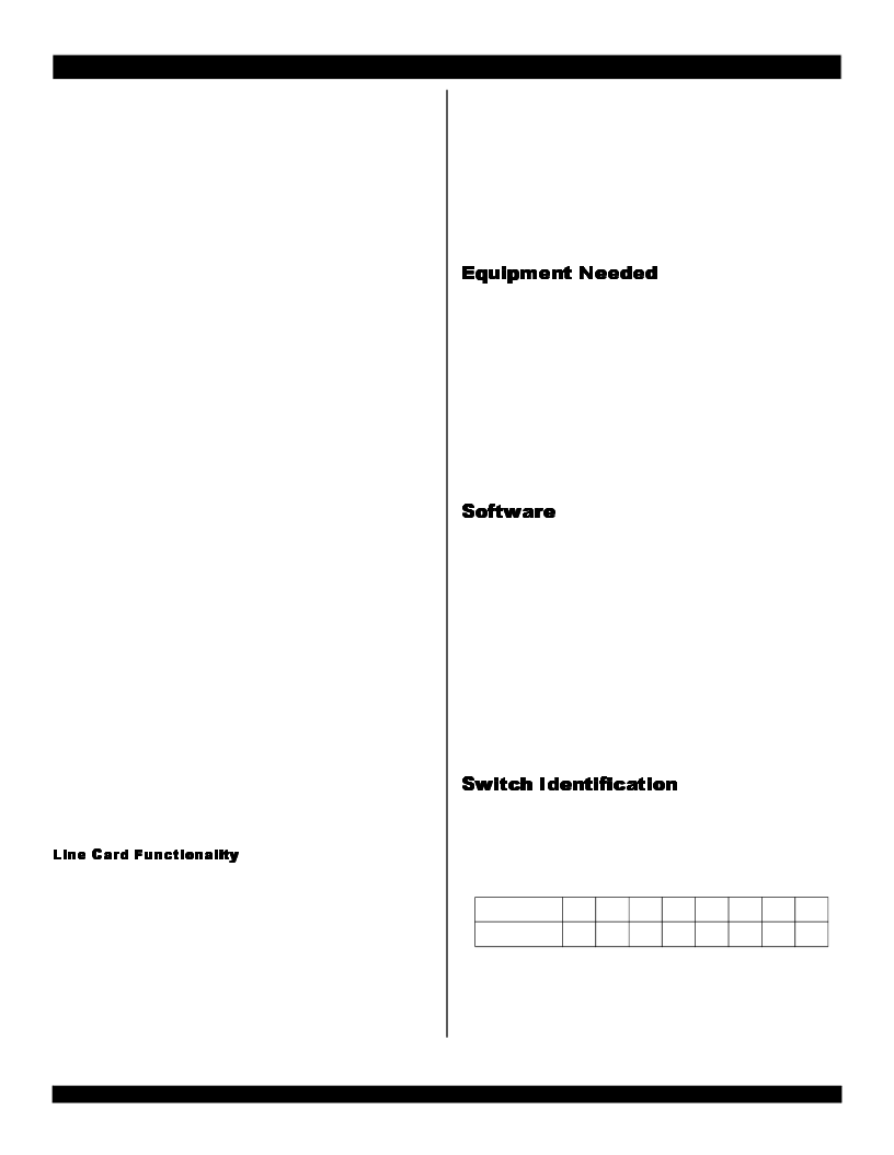
Switch Toggle
1
2
3
4
5
6
7
8
Position
ON
OFF
OFF
OFF
OFF
ON
ON
ON
相关PDF资料 |
PDF描述 |
|---|---|
| IDW100E60 | Fast Switching EmCon Diode |
| IDW75E60 | Fast Switching EmCon Diode |
| IEC-TO-220V-18 | TEANSISTOR INSULATORS |
| IFT3000 | The QUALCOMM IFR3000⑩ and IFT3000⑩ Rx and Tx IF/Baseband processors |
| IFR3000 | The QUALCOMM IFR3000⑩ and IFT3000⑩ Rx and Tx IF/Baseband processors |
相关代理商/技术参数 |
参数描述 |
|---|---|
| IDT77V011L155DA | 功能描述:INTERFACE DPI-UTOPIA 144-TQFP RoHS:否 类别:集成电路 (IC) >> 接口 - 专用 系列:- 标准包装:3,000 系列:- 应用:PDA,便携式音频/视频,智能电话 接口:I²C,2 线串口 电源电压:1.65 V ~ 3.6 V 封装/外壳:24-WQFN 裸露焊盘 供应商设备封装:24-QFN 裸露焊盘(4x4) 包装:带卷 (TR) 安装类型:表面贴装 产品目录页面:1015 (CN2011-ZH PDF) 其它名称:296-25223-2 |
| IDT77V011L155DA8 | 功能描述:INTERFACE DPI-UTOPIA 144-TQFP RoHS:否 类别:集成电路 (IC) >> 接口 - 专用 系列:- 标准包装:3,000 系列:- 应用:PDA,便携式音频/视频,智能电话 接口:I²C,2 线串口 电源电压:1.65 V ~ 3.6 V 封装/外壳:24-WQFN 裸露焊盘 供应商设备封装:24-QFN 裸露焊盘(4x4) 包装:带卷 (TR) 安装类型:表面贴装 产品目录页面:1015 (CN2011-ZH PDF) 其它名称:296-25223-2 |
| IDT77V106L25TF | 制造商:Integrated Device Technology Inc 功能描述: |
| IDT77V106-L25TFI | 制造商:Integrated Device Technology Inc 功能描述:ATM/SONET TRANSCEIVER, 64 Pin, Plastic, QFP |
| IDT77V252L155PG | 制造商:Integrated Device Technology Inc 功能描述:ATM/SONET SEGMENTATION AND REASSEMBLY CIRCUIT, 208 Pin, Plastic, QFP |
发布紧急采购,3分钟左右您将得到回复。