- 您现在的位置:买卖IC网 > PDF目录383106 > IL422-3V (Electronic Theatre Controls, Inc.) Isolated 3Volt RS422/RS485 Interface PDF资料下载
参数资料
| 型号: | IL422-3V |
| 厂商: | Electronic Theatre Controls, Inc. |
| 英文描述: | Isolated 3Volt RS422/RS485 Interface |
| 中文描述: | 隔离3Volt RS422/RS485接口 |
| 文件页数: | 5/7页 |
| 文件大小: | 348K |
| 代理商: | IL422-3V |
Notes:
1.
All Voltage values are with respect to network ground
except differential I/O bus voltages.
Differential input/output voltage is measured at the
noninverting terminal A/Y with respect to the inverting
terminal B/Z.
Skew limit is the maximum difference in any two channels
in one device.
The power-off measurement in ANSI Standard
EIA/TIA-422-B applies to disabled outputs only and is not
applied to combined inputs and outputs.
All typical values are at V
DD
1
,V
2
= 5V and T
A
= 25°C.
The minimum V
OD
2
with a 100
load is either V
OD
1
or
2V, whichever is greater.
|
V
OD
| and
|V
OC
| are the changes in magnitude of V
OD
and V
OC
, respectively, that occur when the input is changed
form one logic state to the other.
This applies for both power on and power off, refer to
ANSI standard RS-485 for exact condition. The EIA/TIA-
422-B limit does not apply for a combined driver and
receiver terminal.
Includes 8 ns read enable time. Maximum propagation
delay is 25 ns after read assertion.
10. Pulse skew is defined as the |t
PLH
-t
PHL
| of each channel.
2.
3.
4.
5.
6.
7.
8.
9.
Application Notes:
Power Consumption
Isoloop
devices achieve their low power consumption from
the manner by which they transmit data across the isolation
barrier. By detecting the edge transitions of the input logic
signal and converting these to narrow current pulses a
magnetic field is created around the GMR Wheatstone
bridge. Depending on the direction of the magnetic field,
the bridge causes the output comparator to switch following
the input logic signal. Since the current pulses are narrow,
about 2.5ns wide, the power consumption is independent of
mark-to-space ratio and solely dependent on frequency. This
has obvious advantages over optocouplers whose power
consumption is heavily dependent on its on-state and
frequency.
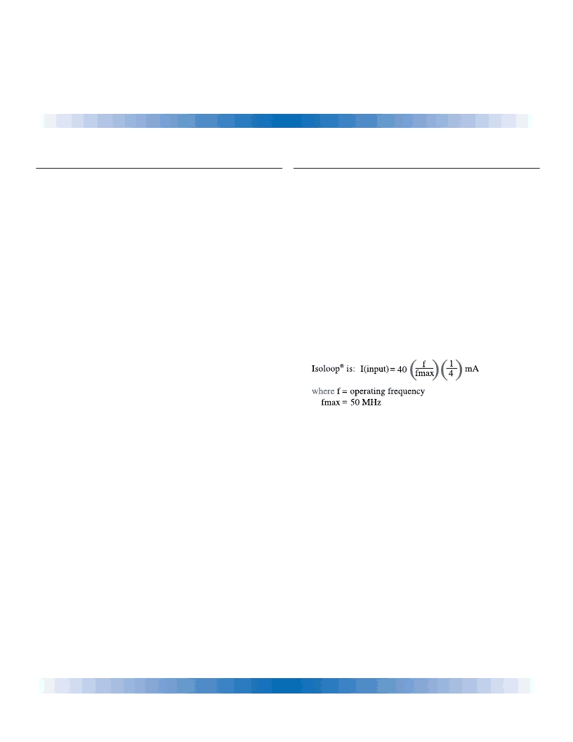
The approximate power supply current per channel for
Power Supplies
It is recommended that low ESR ceramic capacitors be
used to decouple the supplies. Both V
DD
1
and V
DD
2
should
be bypassed with 47 nF capacitors. These should be placed
no further than 1 cm from the device pins for proper
operation. In addition, V
DD
2
should have a 10
μ
F tantalum
capacitor connected in parallel with the 47 nF capacitor.
R H O P O IN T C O M P O N E N T S
5
IL422-3V
I
SO
L
OOP
相关PDF资料 |
PDF描述 |
|---|---|
| IL485 | RES, 1500 OHM 1% 1/8W |
| IL55 | PHOTODARLINGTON OPTOCOUPLER |
| ILQ30 | PHOTODARLINGTON OPTOCOUPLER |
| ILQ31 | PHOTODARLINGTON OPTOCOUPLER |
| ILQ55 | PHOTODARLINGTON OPTOCOUPLER |
相关代理商/技术参数 |
参数描述 |
|---|---|
| IL422E | 功能描述:ISOLATOR HS MAGN RS422 16-SOIC-W RoHS:是 类别:集成电路 (IC) >> 接口 - 驱动器,接收器,收发器 系列:IsoLoop® 标准包装:1 系列:- 类型:线路收发器 驱动器/接收器数:5/3 规程:RS232 电源电压:3 V ~ 5.5 V 安装类型:表面贴装 封装/外壳:28-SOIC(0.295",7.50mm 宽) 供应商设备封装:28-SOIC 包装:Digi-Reel® 产品目录页面:918 (CN2011-ZH PDF) 其它名称:296-25096-6 |
| IL426 | 制造商:未知厂家 制造商全称:未知厂家 功能描述:Optoelectronic |
| IL428 | 制造商:未知厂家 制造商全称:未知厂家 功能描述:Optoelectronic |
| IL440 | 制造商:VISHAY 制造商全称:Vishay Siliconix 功能描述:Optocoupler, Pgototriac Output, Low Input Current |
| IL440_08 | 制造商:VISHAY 制造商全称:Vishay Siliconix 功能描述:Optocoupler, Phototriac Output, Low Input Current |
发布紧急采购,3分钟左右您将得到回复。