- 您现在的位置:买卖IC网 > PDF目录10608 > IL485WE (NVE Corp/Isolation Products)ISOLATOR HS MAG DGTL 16-SOIC-W PDF资料下载
参数资料
| 型号: | IL485WE |
| 厂商: | NVE Corp/Isolation Products |
| 文件页数: | 6/9页 |
| 文件大小: | 0K |
| 描述: | ISOLATOR HS MAG DGTL 16-SOIC-W |
| 产品培训模块: | IsoLoop® Isolator |
| 产品目录绘图: | IL485WE Circuit |
| 特色产品: | Wide-Body SOIC-16 Isolators |
| 标准包装: | 50 |
| 系列: | IsoLoop® |
| 类型: | 收发器,隔离式 |
| 驱动器/接收器数: | 1/1 |
| 规程: | RS485 |
| 电源电压: | 4.5 V ~ 5.5 V |
| 安装类型: | 表面贴装 |
| 封装/外壳: | 16-SOIC(0.295",7.50mm 宽) |
| 供应商设备封装: | 16-SOIC |
| 包装: | 管件 |
| 产品目录页面: | 2771 (CN2011-ZH PDF) |
| 其它名称: | 390-1073-5 |
IL485W
6
NVE Corporation
11409 Valley View Road
Eden Prairie, MN 55344-3617 USA
Telephone: (952) 829-9217
Fax (952) 829-9189
Internet: www.isoloop.com
Application Information
Electromagnetic Compatibility
The IL485W is fully compliant with generic EMC standards
EN50081, EN50082-1 and the umbrella line-voltage standard for
Information Technology Equipment (ITE) EN61000. The
IsoLoop Isolator’s Wheatstone bridge configuration and
differential magnetic field signaling ensure excellent EMC
performance against all relevant standards. NVE conducted
compliance tests in the categories below:
EN50081-1
Residential, Commercial & Light Industrial
Methods EN55022, EN55014
EN50082-2: Industrial Environment
Methods EN61000-4-2 (ESD), EN61000-4-3 (Electromagnetic
Field Immunity), EN61000-4-4 (Electrical Transient Immunity),
EN61000-4-6 (RFI Immunity), EN61000-4-8 (Power Frequency
Magnetic Field Immunity), EN61000-4-9 (Pulsed Magnetic
Field), EN61000-4-10 (Damped Oscillatory Magnetic Field)
ENV50204
Radiated Field from Digital Telephones (Immunity
Test)
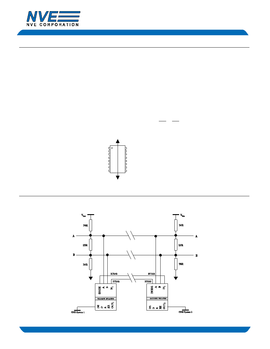
Immunity to external magnetic fields is even higher if
the field direction is “end-to-end” (rather than to
“pin-to-pin”) as shown in the diagram at right.
Dynamic Power Consumption
IsoLoop Isolators achieve their low power consumption from the
way they transmit data across the isolation barrier. By detecting the
edge transitions of the input logic signal and converting these to
narrow current pulses, a magnetic field is created around the GMR
Wheatstone bridge. Depending on the direction of the magnetic
field, the bridge causes the output comparator to switch following
the input logic signal. Since the current pulses are narrow, about
2.5 ns, the power consumption is independent of mark-to-space
ratio and solely dependent on frequency. This has obvious
advantages over optocouplers, which have power consumption
heavily dependent on frequency and time.
The approximate power supply current per channel is:
I
IN = 40 x
f
x
1
mA
Where f = operating frequency
f
MAX = 50 MHz
Power Supply Decoupling
Both VDD1 and VDD2 must be bypassed with 47 nF ceramic
capacitors. These should be placed as close as possible to VDD pins
for proper operation. Additionally, VDD2 should be bypassed with a
10 F tantalum capacitor.
Application
PROFIBUS Fault Interrogation
IL485W
f
MAX
4
相关PDF资料 |
PDF描述 |
|---|---|
| RM15TP-2SA | CONN PLUG 2POS W/SOCKET INSERT |
| IL485E | ISOLATOR HS MAG DGTL 16-SOIC-W |
| RM15TRD-10SB | CONN RECEPT 10POS FOR PCB |
| RM15TP-10S | CONN PLUG 10POS W/SOCKET INSERT |
| VE-JTY-MX-F4 | CONVERTER MOD DC/DC 3.3V 49.5W |
相关代理商/技术参数 |
参数描述 |
|---|---|
| IL485WETR13 | 制造商:RHOPOINT 制造商全称:RHOPOINT COMPONENTS 功能描述:Isolated RS485 Interface With Handshake |
| IL485WTR13 | 制造商:RHOPOINT 制造商全称:RHOPOINT COMPONENTS 功能描述:Isolated RS485 Interface With Handshake |
| IL494 | 制造商:IKSEMICON 制造商全称:IK Semicon Co., Ltd 功能描述:PWM Control Circuit |
| IL494_11 | 制造商:IKSEMICON 制造商全称:IK Semicon Co., Ltd 功能描述:PWM Control Circuit |
| IL494A | 制造商:IKSEMICON 制造商全称:IK Semicon Co., Ltd 功能描述:PWM Control Circuit |
发布紧急采购,3分钟左右您将得到回复。