- 您现在的位置:买卖IC网 > PDF目录6207 > IL611A-3 (NVE Corp/Isolation Products)ISOLATOR PASSIVE INPUT HS 8-SOIC PDF资料下载
参数资料
| 型号: | IL611A-3 |
| 厂商: | NVE Corp/Isolation Products |
| 文件页数: | 8/18页 |
| 文件大小: | 0K |
| 描述: | ISOLATOR PASSIVE INPUT HS 8-SOIC |
| 产品培训模块: | IsoLoop® Isolator |
| 标准包装: | 100 |
| 系列: | IsoLoop® |
| 输入 - 1 侧/2 侧: | 2/0 |
| 通道数: | 2 |
| 电源电压: | 3 V ~ 5.5 V |
| 电压 - 隔离: | 2500Vrms |
| 数据速率: | 10Mbps |
| 传输延迟: | 20ns |
| 输出类型: | 开路漏极 |
| 封装/外壳: | 8-SOIC(0.154",3.90mm 宽) |
| 供应商设备封装: | 8-SOIC(窄型) |
| 包装: | 管件 |
| 工作温度: | -40°C ~ 85°C |
| 其它名称: | 390-1030-5 |
�� �
�
�IL600A� Series� Isolators�
�Non-inverting� and� Inverting� Configurations�
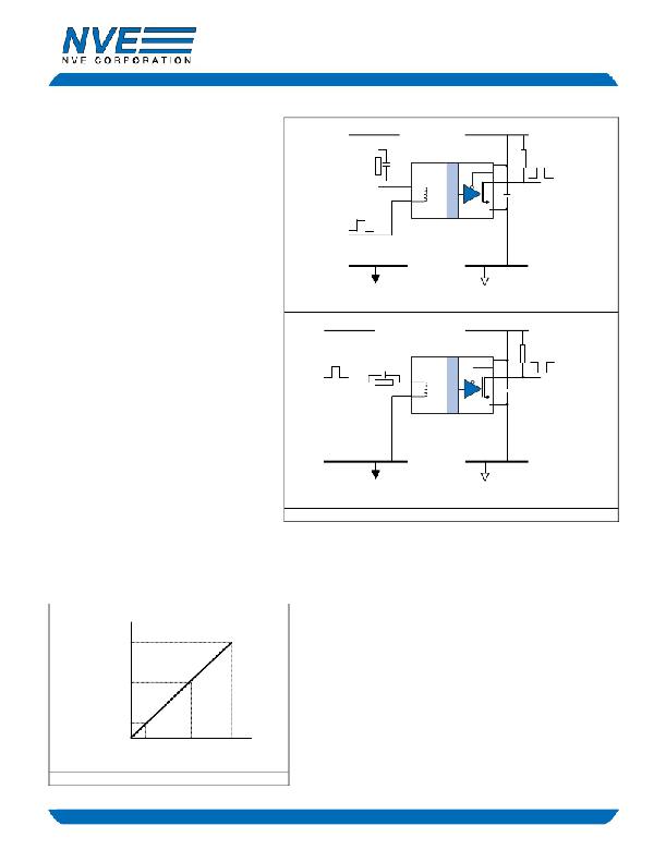
�IL600-Series� Isolators� can� be� configured� in� non-�
�inverting� and� inverting� configurations� (see� Figure�
�3).� In� a� typical� non-inverting� circuit,� the� In� ?�
�terminal� is� connected� via� a� 1� k� ?� input� resistor� to�
�the� supply� rail,� and� the� input� is� connected� to� the� In+�
�terminal.� The� supply� voltage� is� +5� V� and� the� input�
�signal� is� a� 5� V� CMOS� signal.� When� a� logic� high�
�(+5� V)� is� applied� to� the� input,� the� current� through�
�820R�
�+5� V�
�C� boost�
�IL610A�
�3�
�-�
�2� +�
�8�
�7�
�6�
�5�
�V� DD�
�2K�
�Data� Out�
�C� 1�
�the� coil� is� zero.� When� the� input� is� a� logic� low� (0� V),�
�at� least� 5� mA� flows� through� the� coil� from� the� In� ?�
�side� to� the� In+� side.�
�The� inverting� configuration� is� similar� to� standard�
�Data� In�
�logic.� In� the� inverting� configuration,� the� signal� into�
�the� coil� is� differential� with� respect� to� ground.� The�
�designer� must� ensure� that� the� difference� between�
�the� logic� low� voltage� and� the� coil� ground� is� such�
�Non-Inverting� Circuit�
�GND� 1�
�GND� 2�
�Note:� C� 1� is� 47� nF� ceramic.�
�that� the� residual� coil� current� is� less� than� 0.5� mA.�
�The� IL612� and� IL614� devices� have� some� inputs�
�that� do� not� offer� inverting� operation.� The� IL612�
�coil� In� ?� input� is� hardwired� internally� to� the� device�
�power� supply;� therefore� it� is� important� to� ensure� the�
�isolator� power� supply� is� at� the� same� voltage� as� the�
�Data� In�
�+5� V�
�C� boost�
�820R�
�IL610A�
�3�
�-�
�2� +�
�8�
�7�
�6�
�5�
�V� DD�
�2K�
�Data� Out�
�C� 1�
�power� supply� to� the� source� of� the� input� logic� signal.�
�The� IL614� has� a� common� coil� In� ?� for� two� inputs.�
�This� pin� should� be� connected� to� the� power� supply�
�for� the� logic� driving� channels� 2� and� 3,� and� the�
�channels� run� should� be� run� in� non-inverting� mode.�
�Both� single� ended� and� differential� inputs� can� be�
�handled� without� reverse� bias� protection.�
�Inverting� Circuit�
�GND� 1�
�GND� 2�
�Note:� C� 1� is� 47� nF� ceramic.�
�Figure� 3.� Non-inverting� and� inverting� circuits�
�Boost� Capacitor�
�The� boost� capacitor� in� parallel� with� the� current-limiting� resistor� boosts� the� instantaneous� coil� current� at� the� signal� transition.� This�
�ensures� switching� and� reduces� propagation� delay� and� reduces� pulse-width� distortion.�
�Select� the� value� of� the� boost� capacitor� based� on� the� rise� and� fall�
�times� of� the� signal� driving� the� inputs.� The� instantaneous� boost�
�1000�
�Signal�
�Rise/Fall� Time� (ns)�
�500�
�capacitor� current� is� proportional� to� input� edge� speeds� (� C� dVdt� ).� Select� a�
�capacitor� value� based� on� the� rise� and� fall� times� of� the� input� signal� to� be�
�isolated� that� provides� approximately� 20� mA� of� additional� “boost”�
�current.� Figure� 4� is� a� guide� to� boost� capacitor� selection.� For� high-speed�
�logic� signals� (t� r� ,t� f� <� 10� ns),� a� 16� pF� capacitor� is� recommended.� The�
�capacitor� value� is� generally� not� critical;� if� in� doubt,� choose� a� higher�
�value.�
�3�
�16�
�2500�
�5000�
�C� Boost� (pF)�
�Figure� 4.� C� boost� Selector�
�8�
�NVE� Corporation�
�11409� Valley� View� Road,� Eden� Prairie,� MN� 55344-3617�
�Phone:� (952)� 829-9217�
�Fax:� (952)� 829-9189�
�www.IsoLoop.com�
�?NVE� Corporation�
�相关PDF资料 |
PDF描述 |
|---|---|
| IL611A-2 | ISOLATOR PASSIVE INPUT HS 8-DIP |
| IL611A-1 | ISOLATOR PASSIVE INPUT HS 8-MSOP |
| IL610A-3 | ISOLATOR PASSIVE INPUT HS 8-SOIC |
| IL610A-2 | ISOLATOR PASSIVE INPUT HS 8-DIP |
| IL610A-1 | ISOLATOR PASSIVE INPUT HS 8-MSOP |
相关代理商/技术参数 |
参数描述 |
|---|---|
| IL611A-3E | 功能描述:ISOLATOR PASSIVE INPUT HS 8SOIC RoHS:是 类别:隔离器 >> 数字隔离器 系列:IsoLoop® 标准包装:66 系列:iCoupler® 输入 - 1 侧/2 侧:2/2 通道数:4 电源电压:3.3V,5V 电压 - 隔离:2500Vrms 数据速率:25Mbps 传输延迟:60ns 输出类型:逻辑 封装/外壳:20-SSOP(0.209",5.30mm 宽) 供应商设备封装:20-SSOP 包装:管件 工作温度:-40°C ~ 105°C |
| IL611A-3ETR13 | 制造商:未知厂家 制造商全称:未知厂家 功能描述:Passive Input Digital Isolators |
| IL611A-3ETR7 | 制造商:未知厂家 制造商全称:未知厂家 功能描述:Passive Input Digital Isolators |
| IL611A-3TR13 | 制造商:未知厂家 制造商全称:未知厂家 功能描述:Passive Input Digital Isolators |
| IL611A-3TR7 | 制造商:未知厂家 制造商全称:未知厂家 功能描述:Passive Input Digital Isolators |
发布紧急采购,3分钟左右您将得到回复。