- 您现在的位置:买卖IC网 > PDF目录61110 > IL755-2-X001 (VISHAY INTERTECHNOLOGY INC) 1 CHANNEL AC INPUT-DARLINGTON OUTPUT OPTOCOUPLER PDF资料下载
参数资料
| 型号: | IL755-2-X001 |
| 厂商: | VISHAY INTERTECHNOLOGY INC |
| 元件分类: | 光电耦合器 |
| 英文描述: | 1 CHANNEL AC INPUT-DARLINGTON OUTPUT OPTOCOUPLER |
| 封装: | DIP-6 |
| 文件页数: | 1/3页 |
| 文件大小: | 378K |
| 代理商: | IL755-2-X001 |
Document Number: 83641
www.vishay.com
Revision 17-August-01
2–154
FEATURES
High Current Transfer Ratios, VCE=5.0 V
IL/ILD755-1: 750% at IF=2.0 mA
IL/ILD755-2: 1000% at IF=1.0 mA
BVCEO >60 V
AC or Polarity Insensitive Inputs
Built-In Reverse Polarity Input Protection
Industry Standard DIP Package
Underwriters Lab File #E52744
VDE #0884 Available with Option 1
DESCRIPTION
The IL/ILD755 are bidirectional input optically cou-
pled isolators. They consist of two Gallium Ars-
enide infrared emitting diodes coupled to a silicon
NPN photodarlington per channel.
The IL755 are single channel Darlington optocou-
plers. The ILD755 has two isolated channels in a
single DIP package.
They are designed for applications requiring
detection or monitoring of AC signals.
Maximum Ratings
Emitter (Each Channel)
Continuous Forward Current ......................... 60 mA
Power Dissipation at 25
°C.......................... 100 mW
Derate Linearly from 25
°C.................... 1.33 mW/°C
Detector (Each Channel)
Collector-Emitter Breakdown Voltage............... 60 V
Collector-Base Breakdown Voltage ................. 60 V
Power Dissipation at 25
°C
IL755 ......................................................... 200 mW
ILD755 ...................................................... 150 mW
Derate Linearly from 25
°C
ILD755 .................................................. 2.6 mW/
°C
ILD755 .................................................. 2.0 mW/
°C
Package
Isolation Test Voltage (PK)
(t=1.0 sec.) ...................... 7500 VACPK/5300 VRMS
Total Power Dissipation at 25
°C Ambient
(LED Plus Detector)
IL755 ......................................................... 250 mW
ILD755 ...................................................... 400 mW
Derate Linearly from 25
°C
IL7553 ................................................... 3.0 mW/
°C
ILD7555 ................................................ 3.0 mW/
°C
Creepage .................................................
≥7.0 mm
Clearance .................................................
≥7.0 mm
Storage Temperature.................... –55
°C to +150°C
Operating Temperature ................ –55
°C to +100°C
Lead Soldering Time at 260
°C .................... 10 sec.
V
DE
Electrical Characteristics TA=25°C
Symbol
Min.
Typ.
Max.
Unit
Condition
Emitter
Forward Voltage
VF
—
1.2
1.5
V
IF=±10 mA
Detector
—BVCEO
60
75
—
V
IC=1.0 mA
—BVCBO
60
90
—
IC=10 A
—
ICEO
—
10
100
nA
VCE=10 V
Package
—
VCEsat
—
1.0
—
IF=±10 mA,
IC=10 mA
DC Current
Transfer Ratio
IL755/ILD755-1
IL755/ILD755-2
CTR
750
1000
——
%
VCE=5.0 V
IF=±2.0 mA,
IF=±1.0 mA,
Rise Time/Fall Time
IL/ILD755-1
IL/ILD755-2
——
50
70
—
s
VCC=10 V,
RL=100 ,
IF=2.0 mA
IF=1.0 mA
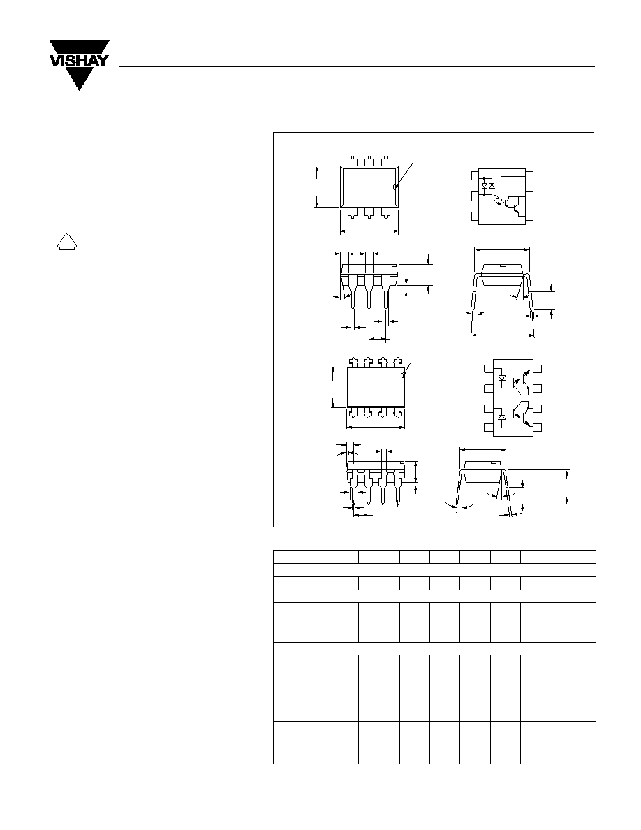
.010 (.25)
typ.
.114 (2.90)
.130 (3.0)
.130 (3.30)
.150 (3.81)
.031 (0.80) min.
.300 (7.62)
typ.
.031 (0.80)
.035 (0.90)
.100 (2.54) typ.
.039
(1.00)
Min.
.018 (0.45)
.022 (0.55)
.048 (0.45)
.022 (0.55)
.248 (6.30)
.256 (6.50)
.335 (8.50)
.343 (8.70)
pin one ID
6
5
4
1
2
3
18
°
3
°–9°
.300–.347
(7.62–8.81)
4
°
typ.
pin one ID
.255 (6.48)
.268 (6.81)
.379 (9.63)
.390 (9.91)
.030 (0.76)
.045 (1.14)
4
° typ.
.100 (2.54) typ.
10
°
3
°–9°
.300 (7.62)
typ.
.018 (.46)
.022 (.56)
.008 (.20)
.012 (.30)
.110 (2.79)
.130 (3.30)
.150 (3.81)
.020 (.51 )
.035 (.89 )
.230(5.84)
.250(6.35)
4
3
2
1
.031 (0.79)
.050 (1.27)
5
6
78
8
7
6
5
Emitter
Collector
Emitter
Anode
Cathode
Anode
1
2
3
4
1
2
3
6
5
4
Anode/
Cathode
Cathode/
Anode
NC
Base
Collector
Emitter
Dimensions in inches (mm)
Single Channel
Dual Channel
SINGLE CHANNEL
IL755
DUAL CHANNEL
ILD755
Bidirectional Input
Darlington Optocoupler
相关PDF资料 |
PDF描述 |
|---|---|
| ILD766-1 | 2 CHANNEL AC INPUT-DARLINGTON OUTPUT OPTOCOUPLER |
| ILL5A0001G | SINGLE COLOR DISPLAY CLUSTER, RED |
| ILQ1-X009 | 4 CHANNEL TRANSISTOR OUTPUT OPTOCOUPLER |
| ILD1-X006 | 2 CHANNEL TRANSISTOR OUTPUT OPTOCOUPLER |
| ILD2-X006 | 2 CHANNEL TRANSISTOR OUTPUT OPTOCOUPLER |
相关代理商/技术参数 |
参数描述 |
|---|---|
| IL755-2X007T | 制造商:Vishay Angstrohm 功能描述:Optocoupler AC-IN 1-CH Darlington With Base DC-OUT 6-Pin PDIP SMD T/R 制造商:Vishay Semiconductors 功能描述:SMD-6 CPL DARLINGTON CTR>1000% -E3 - Tape and Reel |
| IL755B | 制造商:INFINEON 制造商全称:Infineon Technologies AG 功能描述:BIDIRECTIONAL INPUT DARLINGTON OPTOCOUPLER |
| IL755B-1 | 制造商:Vishay Angstrohm 功能描述:Optocoupler AC-IN 1-CH Darlington DC-OUT 6-Pin PDIP 制造商:Vishay Semiconductors 功能描述:Optocoupler |
| IL755B-2 | 制造商:Vishay Angstrohm 功能描述:Optocoupler AC-IN 1-CH Darlington DC-OUT 6-Pin PDIP 制造商:Vishay Semiconductors 功能描述:Optocoupler |
| IL7650SCJD | 制造商:Rochester Electronics LLC 功能描述:- Bulk |
发布紧急采购,3分钟左右您将得到回复。