- 您现在的位置:买卖IC网 > PDF目录61099 > IL755B (INFINEON TECHNOLOGIES AG) 1 CHANNEL DARLINGTON OUTPUT OPTOCOUPLER PDF资料下载
参数资料
| 型号: | IL755B |
| 厂商: | INFINEON TECHNOLOGIES AG |
| 元件分类: | 光电耦合器 |
| 英文描述: | 1 CHANNEL DARLINGTON OUTPUT OPTOCOUPLER |
| 封装: | PLASTIC, DIP-6 |
| 文件页数: | 1/2页 |
| 文件大小: | 42K |
| 代理商: | IL755B |
5–1
FEATURES
Very High Current Transfer Ratio (500% min.)
IL755B-1: 750% at IF=2 mA, VCE=5 V
IL755B-2: 1000% at IF=1 mA, VCE=5 V
BVCEO >60 V
Isolation Test Voltage, 5300 VACRMS
AC or Polarity Insensitive Inputs
No Base Connection
High Isolation Resistance, 1012
Low Coupling Capacitance
Standard Plastic DIP Package
Underwriters Lab Approval #E52744
VDE #0884 Available with Option 1
DESCRIPTION
The IL755B is a bidirectional input, optically cou-
pled isolator consisting of two Gallium Arsenide
infrared emitters and a silicon photodarlington sen-
sor.
Maximum Ratings (at 25
°C)
Emitter (Drive Circuit)
Continuous Forward Current .........................60 mA
Power Dissipation at 25
°C..........................100 mW
Derate Linearly from 55
°C....................1.33 mW/°C
Detector
Collector-Emitter Breakdown Voltage ..............60 V
Emitter-Collector Breakdown Voltage ..............12 V
Power Dissipation at 25
°C Ambient ...........200 mW
Derate Linearly from 25
°C......................2.6 mW/°C
Package
Isolation Test Voltage
(PK), t=1 sec.................................. 5300 VACRMS
Dissipation at 25
°C.....................................250 mW
Derate Linearly from 25
°C(2) .................3.3 mW/°C
Creepage ................................................ 7 min mm
Clearance................................................ 7 min mm
Isolation Resistance
TA=25°C.................................................. ≥10
12
TA=100°C................................................ ≥10
11
Storage Temperature(2) ..............–55
°C to +150°C
Operating Temperature ................–55
°C to +100°C
Lead Soldering Time at 260
°C .................... 10 sec.
Electrical Characteristics (TA=25°C)
Notes:
1. Indicates JEDEC registered data.
Symbol
Min.
Typ.
Max.
Unit
Condition
Emitter
Forward Voltage(1)
VF
1.25
1.5
V
IF=10 mA
Detector(2)
Breakdown Voltage,
Collector-Emitter
BVCEO
60
75
V
IC=1 mA,
IF=0
Leakage Current,
Collector-Emitter
ICEO
1.0
100
nA
VCE=10 V,
IF=0
Package
Current Transfer
Ratio(2)
IL755B-1
IL755B-2
CTR
750
1000
%
IF=±2 mA,
VCE=5 V
IF=±1 mA,
VCE=5 V
Saturation Voltage,
Collector-Emitter
VCEsat
1.0
V
IC=10 mA,
IF=±10 mA
Turn-On Time
ton
200
sV
CC=10 V
Turn-Off Time
toff
200
sI
F=± 2 mA,
RL=100
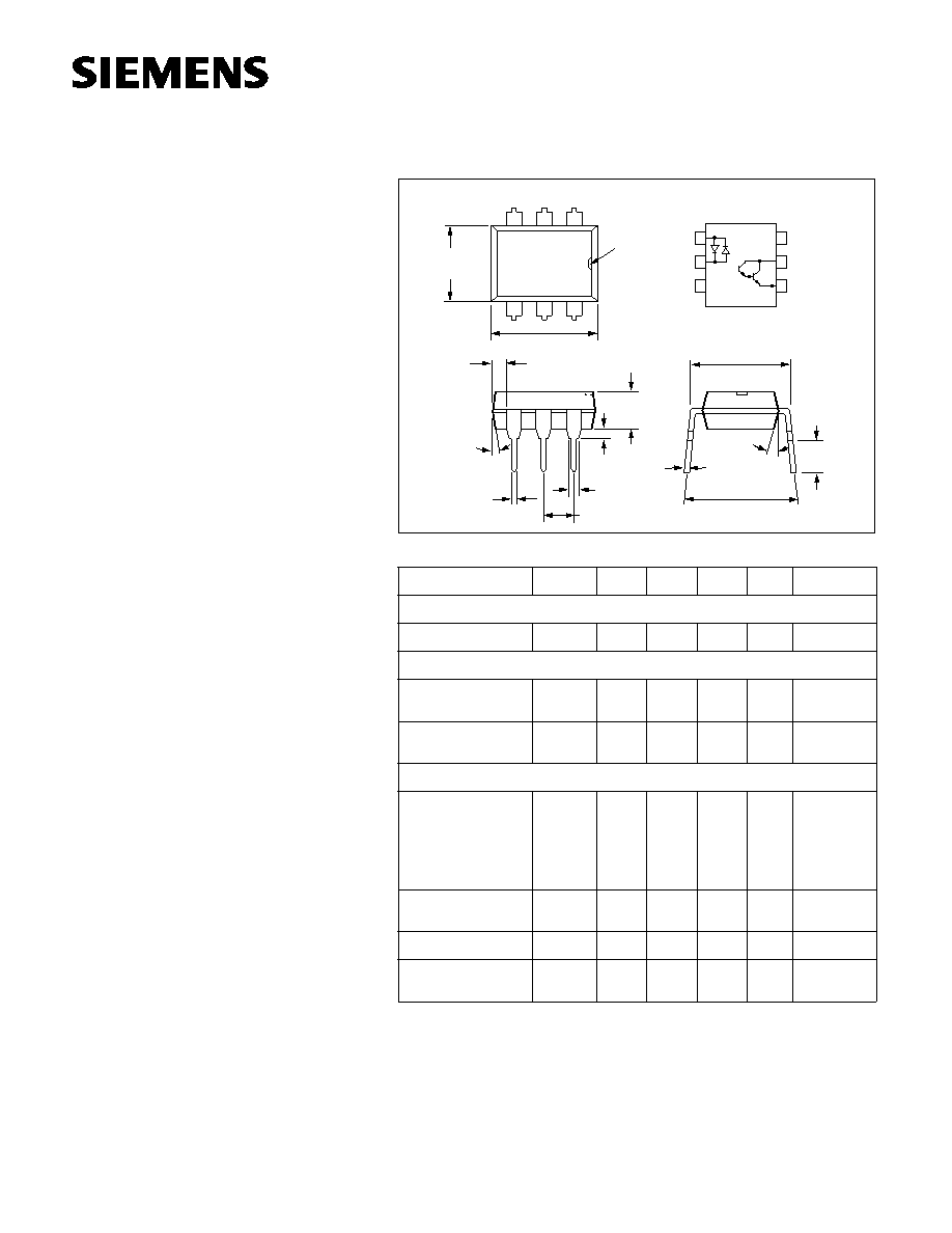
Dimensions in inches (mm)
1
2
3
6
5
4
Base
Collector
Emitter
Anode/
Cathode
Catho e/
Anode
NC
.010 (.25)
.014 (.35)
.114(2.90)
.130 (3.30)
.138 (3.50)
.032 (0.80)
Min.
.300 (7.62)
Typ.
.031 (0.80)
.035 (0.90)
.100 (2.54) Typ.
.039
(1.00)
Min.
.018 (0.45)
.022 (0.55)
.248 (6.30)
.256 (6.50)
.335 (8.50)
.343 (8.70)
6
5
4
1
2
3
18
° Typ.
.300 (7.62)
.347 (8.82)
4
°
Typ.
pin one
ID.
IL755B
BIDIRECTIONAL INPUT
DARLINGTON OPTOCOUPLER
相关PDF资料 |
PDF描述 |
|---|---|
| IL755 | 1 CHANNEL DARLINGTON OUTPUT OPTOCOUPLER |
| IL766-1-X006 | 1 CHANNEL AC INPUT-DARLINGTON OUTPUT OPTOCOUPLER |
| IL766-1-X007T | 1 CHANNEL AC INPUT-DARLINGTON OUTPUT OPTOCOUPLER |
| IL766-2-X006 | 1 CHANNEL AC INPUT-DARLINGTON OUTPUT OPTOCOUPLER |
| IL766-1-X019T | 1 CHANNEL AC INPUT-DARLINGTON OUTPUT OPTOCOUPLER |
相关代理商/技术参数 |
参数描述 |
|---|---|
| IL755B-1 | 制造商:Vishay Angstrohm 功能描述:Optocoupler AC-IN 1-CH Darlington DC-OUT 6-Pin PDIP 制造商:Vishay Semiconductors 功能描述:Optocoupler |
| IL755B-2 | 制造商:Vishay Angstrohm 功能描述:Optocoupler AC-IN 1-CH Darlington DC-OUT 6-Pin PDIP 制造商:Vishay Semiconductors 功能描述:Optocoupler |
| IL7650SCJD | 制造商:Rochester Electronics LLC 功能描述:- Bulk |
| IL766 | 制造商:VISHAY 制造商全称:Vishay Siliconix 功能描述:Optocoupler, Photodarlington Output, AC Input, Internal RBE |
| IL766-1 | 功能描述:晶体管输出光电耦合器 Photodarlington Out Single CTR >500% RoHS:否 制造商:Vishay Semiconductors 输入类型:DC 最大集电极/发射极电压:70 V 最大集电极/发射极饱和电压:0.4 V 绝缘电压:5300 Vrms 电流传递比:100 % to 200 % 最大正向二极管电压:1.65 V 最大输入二极管电流:60 mA 最大集电极电流:100 mA 最大功率耗散:100 mW 最大工作温度:+ 110 C 最小工作温度:- 55 C 封装 / 箱体:DIP-4 封装:Bulk |
发布紧急采购,3分钟左右您将得到回复。