- 您现在的位置:买卖IC网 > PDF目录383110 > IP82C54-10 (INTERSIL CORP) CMOS Programmable Interval Timer PDF资料下载
参数资料
| 型号: | IP82C54-10 |
| 厂商: | INTERSIL CORP |
| 元件分类: | XO, clock |
| 英文描述: | CMOS Programmable Interval Timer |
| 中文描述: | 3 TIMER(S), PROGRAMMABLE TIMER, PDIP24 |
| 封装: | PLASTIC, MS-011AA, DIP-24 |
| 文件页数: | 6/17页 |
| 文件大小: | 142K |
| 代理商: | IP82C54-10 |
4-6
A new initial count may be written to a Counter at any time
without affecting the Counter’s programmed Mode in any way.
Counting will be affected as described in the Mode definitions.
The new count must follow the programmed count format.
If a Counter is programmed to read/write two-byte counts,
the following precaution applies. A program must not transfer
control between writing the first and second byte to another
routine which also writes into that same Counter. Otherwise,
the Counter will be loaded with an incorrect count.
Read Operations
It is often desirable to read the value of a Counter without
disturbing the count in progress. This is easily done in the
82C54.
There are three possible methods for reading the Counters.
The first is through the Read-Back command, which is
explained later. The second is a simple read operation of the
Counter, which is selected with the A1, A0 inputs. The only
requirement is that the CLK input of the selected Counter
must be inhibited by using either the GATE input or external
logic. Otherwise, the count may be in process of changing
when it is read, giving an undefined result.
Counter Latch Command
The other method for reading the Counters involves a spe-
cial software command called the “Counter Latch Com-
mand”. Like a Control Word, this command is written to the
Control Word Register, which is selected when A1, A0 = 11.
Also, like a Control Word, the SC0, SC1 bits select one of
the three Counters, but two other bits, D5 and D4, distin-
guish this command from a Control Word.
.
A1, A0 = 11; CS = 0; RD = 1; WR = 0
The selected Counter’s output latch (OL) latches the count
when the Counter Latch Command is received. This count is
held in the latch until it is read by the CPU (or until the Counter
is reprogrammed). The count is then unlatched automatically
and the OL returns to “following” the counting element (CE).
This allows reading the contents of the Counters “on the fly”
without affecting counting in progress. Multiple Counter Latch
Commands may be used to latch more than one Counter.
Each latched Counter’s OL holds its count until read. Counter
Latch Commands do not affect the programmed Mode of the
Counter in any way.
If a Counter is latched and then, some time later, latched
again before the count is read, the second Counter Latch
Command is ignored. The count read will be the count at the
time the first Counter Latch Command was issued.
With either method, the count must be read according to the
programmed format; specifically, if the Counter is pro-
grammed for two byte counts, two bytes must be read. The
two bytes do not have to be read one right after the other;
read or write or programming operations of other Counters
may be inserted between them.
Another feature of the 82C54 is that reads and writes of the
same Counter may be interleaved; for example, if the
Counter is programmed for two byte counts, the following
sequence is valid.
LSB of Count - Counter 1
0
1
LSB of Count - Counter 0
0
0
MSB of Count - Counter 0
0
0
MSB of Count - Counter 1
0
1
MSB of Count - Counter 2
1
0
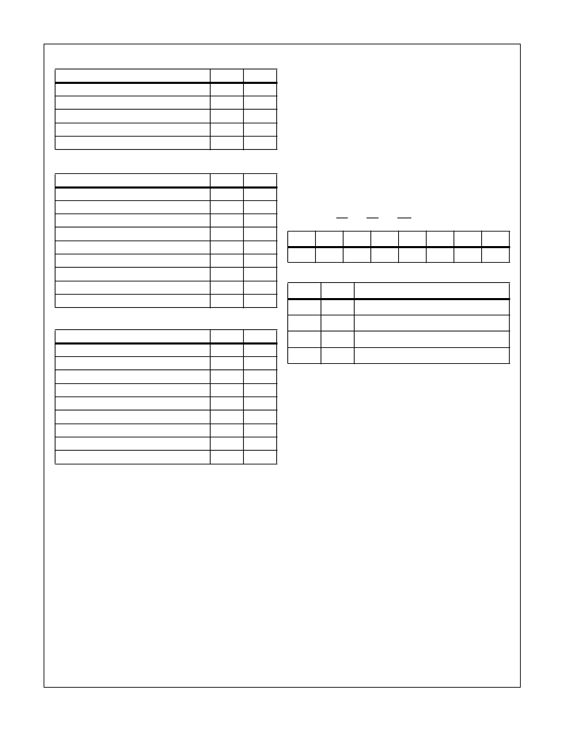
Possible Programming Sequence
A1
A0
Control Word - Counter 2
1
1
Control Word - Counter 1
1
1
Control Word - Counter 0
1
1
LSB of Count - Counter 2
1
0
MSB of Count - Counter 2
1
0
LSB of Count - Counter 1
0
1
MSB of Count - Counter 1
0
1
LSB of Count - Counter 0
0
0
MSB of Count - Counter 0
0
0
Possible Programming Sequence
A1
A0
Control Word - Counter 1
1
1
Control Word - Counter 0
1
1
LSB of Count - Counter 1
0
1
Control Word - Counter 2
1
1
LSB of Count - Counter 0
0
0
MSB of Count - Counter 1
0
1
LSB of Count - Counter 2
1
0
MSB of Count - Counter 0
0
0
MSB of Count - Counter 2
1
0
NOTE: In all four examples, all counters are programmed to
Read/Write two-byte counts. These are only four of many
programming sequences.
Possible Programming Sequence
(Continued)
A1
A0
D7
D6
D5
D4
D3
D2
D1
D0
SC1
SC0
0
0
X
X
X
X
SC1, SC0 - specify counter to be latched
SC1
SC0
COUNTER
0
0
0
0
1
1
1
0
2
1
1
Read-Back Command
D5, D4 - 00 designates Counter Latch Command, X - Don’t Care.
NOTE: Don’t Care bits (X) should be 0 to insure compatibility with
future products.
82C54
相关PDF资料 |
PDF描述 |
|---|---|
| IP82C59A | CMOS Priority Interrupt Controller |
| IP82C59A-5 | CMOS Priority Interrupt Controller |
| IP82C59A-12 | CMOS Priority Interrupt Controller |
| IP82C83H | CMOS Octal Latching Inverting Bus Driver |
| IP82C84A | CMOS Clock Generator Driver |
相关代理商/技术参数 |
参数描述 |
|---|---|
| IP82C54-10S5001 | 制造商:Rochester Electronics LLC 功能描述:- Bulk |
| IP82C54-10Z | 功能描述:计时器和支持产品 W/ANNEAL PERIPH PRG- CNTR 5V 10MHZ 24PDIP RoHS:否 制造商:Micrel 类型:Standard 封装 / 箱体:SOT-23 内部定时器数量:1 电源电压-最大:18 V 电源电压-最小:2.7 V 最大功率耗散: 最大工作温度:+ 85 C 最小工作温度:- 40 C 封装:Reel |
| IP82C54-12 | 制造商:INTERSIL 制造商全称:Intersil Corporation 功能描述:CMOS Programmable Interval Timer |
| IP82C54Z | 功能描述:计时器和支持产品 W/ANNEAL PERIPH PRG- CNTR 5V 8MHZ RoHS:否 制造商:Micrel 类型:Standard 封装 / 箱体:SOT-23 内部定时器数量:1 电源电压-最大:18 V 电源电压-最小:2.7 V 最大功率耗散: 最大工作温度:+ 85 C 最小工作温度:- 40 C 封装:Reel |
| IP82C55A | 功能描述:外围驱动器与原件 - PCI PERIPH PRG-I/O 5V 8MHZ IND RoHS:否 制造商:PLX Technology 工作电源电压: 最大工作温度: 安装风格:SMD/SMT 封装 / 箱体:FCBGA-1156 封装:Tray |
发布紧急采购,3分钟左右您将得到回复。