- 您现在的位置:买卖IC网 > PDF目录1808 > IR2156STR (International Rectifier)IC BALLAST CONT 600V .5A 14-SOIC PDF资料下载
参数资料
| 型号: | IR2156STR |
| 厂商: | International Rectifier |
| 文件页数: | 17/21页 |
| 文件大小: | 0K |
| 描述: | IC BALLAST CONT 600V .5A 14-SOIC |
| 标准包装: | 2,500 |
| 类型: | 镇流器控制器 |
| 频率: | 28 ~ 32 kHz |
| 电流 - 电源: | 1mA |
| 电源电压: | 11.5 V ~ 15.6 V |
| 工作温度: | -40°C ~ 125°C |
| 封装/外壳: | 14-SOIC(0.154",3.90mm 宽) |
| 供应商设备封装: | 14-SOIC(窄型) |
| 包装: | 带卷 (TR) |
| 配用: | IRPLCFL4-ND - IC BALLAST DIMMING CFL 3-WAY IRPLCFL3-ND - KIT DESIGN CFL TRIAC DIMMING |
�� �
�
�IR2156(S)PbF�
�Functional� Description�
�Under-voltage� Lock-out� Mode� (UVLO)�
�The� under-voltage� lock-out� mode� (UVLO)� is� defined� as� the�
�state� the� IC� is� in� when� VCC� is� below� the� turn-on� threshold� of� the�
�IC.� To� identify� the� different� modes� of� the� IC,� refer� to� the� State�
�Diagram� shown� on� page� 2� of� this� document.� The� IR2156�
�undervoltage� lock-out� is� designed� to� maintain� an� ultra� low� supply�
�current� of� less� than� 200uA,� and� to� guarantee� the� IC� is� fully�
�functional� before� the� high� and� low� side� output� drivers� are�
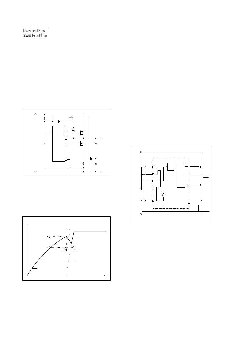
�activated.� Figure� 1� shows� an� efficient� supply� voltage� using� the�
�start-up� current� of� the� IRS2156� together� with� a� charge� pump� from�
�the� ballast� output� stage� (R� SUPPLY� ,� C� VCC� ,� D� CP1� and� D� CP2� ).�
�V� BUS� (+)�
�current� is� available� over� all� ballast� operating� conditions.� An�
�external� bootstrap� diode� (D� BOOT� )� and� the� supply� capacitor� (C� BOOT� )�
�comprise� the� supply� voltage� for� the� high� side� driver� circuitry.� To�
�guarantee� that� the� high-side� supply� is� charged� up� before� the� first�
�pulse� on� pin� HO,� the� first� pulse� from� the� output� drivers� comes�
�from� the� LO� pin.� During� undervoltage� lock-out� mode,� the� high-�
�and� low-side� driver� outputs� HO� and� LO� are� both� low,� pin� CT� is�
�connected� internally� to� COM� to� disable� the� oscillator,� and� pin�
�CPH� is� connected� internally� to� COM� for� resetting� the� preheat�
�time.�
�Preheat� Mode� (PH)�
�The� preheat� mode� is� defined� as� the� state� the� IC� is� in� when�
�the� lamp� filaments� are� being� heated� to� their� correct� emission�
�temperature.� This� is� necessary� for� maximizing� lamp� life� and�
�reducing� the� required� ignition� voltage.� The� IR2156� enters� preheat�
�mode� when� VCC� exceeds� the� VCCUV+� positive-going� threshold.�
�R� SUPPLY�
�D� BOOT�
�R� LIM�
�HO� and� LO� begin� to� oscillate� at� the� preheat� frequency� with� 50%�
�duty� cycle� and� with� a� dead-time� which� is� set� by� the� value� of� the�
�VCC�
�14�
�VB�
�HO�
�C� BOOT�
�external� timing� capacitor,� CT,� and� internal� deadtime� resistor,�
�RDT.� Pin� CPH� is� disconnected� from� COM� and� an� internal� 4uA�
�2�
�13�
�12�
�VS�
�M1�
�Half-Bridge�
�Output�
�current� source� (Figure� 3)� charges� the� external� preheat� timing�
�capacitor� on� CPH� linearly.� The� over-current� protection� on� pin� CS�
�C� VCC�
�11�
�LO�
�M2�
�is� disabled� during� preheat.�
�C� SNUB�
�V� BUS� (+)�
�COM�
�8�
�R� CS�
�D� CP1�
�D� CP2�
�RT�
�4�
�OSC.�
�13�
�HO�
�M1�
�V� BUS� (-)�
�RT�
�RPH�
�RPH�
�5�
�S4�
�Half-�
�Bridge�
�Driver�
�12�
�VS�
�Half�
�Bridge�
�Output�
�Figure� 1,� Start-up� and� supply� circuitry.�
�CT�
�6�
�I� LOAD�
�The� start-up� capacitor� (C� VCC� )� is� charged� by� current� through�
�supply� resistor� (R� SUPPLY� )� minus� the� start-up� current� drawn� by� the�
�CT�
�11�
�LO�
�M2�
�IC.� This� resistor� is� chosen� to� provide� 2X� the� maximum� start-up�
�5uA�
�current� to� guarantee� ballast� start-up� at� low� line� input� voltage.�
�Once� the� capacitor� voltage� on� VCC� reaches� the� start-up� threshold�
�VCCUV+,� and� the� SD� pin� is� below� VSDTH-,� the� IC� turns� on� and�
�CPH�
�CPH�
�7�
�8�
�COM�
�RCS�
�HO� and� LO� begin� to� oscillate.� The� capacitor� begins� to� discharge�
�due� to� the� increase� in� IC� operating� current� (Figure� 2).�
�V� C1�
�V� BUS� (-)�
�Load�
�Return�
�V� ccuv+�
�VCCHYS�
�V� ccuv-�
�C� VCC�
�DISCHARGE�
�INTERNAL� VCC�
�ZENER� CLAMP� VOLTAGE�
�DISCHARGE�
�TIME�
�Figure� 3,� Preheat� circuitry�
�The� preheat� frequency� is� determined� by� the� parallel�
�combination� of� resistors� RT� and� RPH,� together� with� timing�
�capacitor� CT.� CT� charges� and� discharges� between� 1/3� and� 3/5� of�
�VCC� (see� Timing� Diagram,� page� 9).� CT� is� charged� exponentially�
�through� the� parallel� combination� of� RT� and� RPH� connected�
�internally� to� VCC� through� MOSFET� S1.� The� charge� time� of� CT�
�from� 1/3� to� 3/5� VCC� is� the� on-time� of� the� respective� output� gate�
�CHARGE� PUMP�
�OUTPUT�
�R� SUPPLY� &� C� VCC�
�TIME�
�CONSTANT�
�t�
�Figure� 2,� Supply� capacitor� (C� VCC� )� voltage.�
�During� the� discharge� cycle,� the� rectified� current� from� the�
�charge� pump� charges� the� capacitor� above� the� IC� turn-off�
�threshold.� The� charge� pump� and� the� internal� 15.6V� zener� clamp�
�of� the� IC� take� over� as� the� supply� voltage.� The� start-up� capacitor�
�and� snubber� capacitor� must� be� selected� such� that� enough� supply�
�17�
�driver,� HO� or� LO.� Once� CT� exceeds� 3/5� VCC,� MOSFET� S1� is�
�turned� off,� disconnecting� RT� and� RPH� from� VCC.� CT� is� then�
�discharged� exponentially� through� an� internal� resistor,� RDT,�
�through� MOSFET� S3� to� COM.� The� discharge� time� of� CT� from� 3/5�
�to� 1/3� VCC� is� the� dead-time� (both� off)� of� the� output� gate� drivers,�
�HO� and� LO.� The� selected� value� of� CT� together� with� RDT�
�therefore� program� the� desired� dead-time� (see� Design� Equations,�
�page� 12,� Equations� 1� and� 2).� Once� CT� discharges� below� 1/3�
�VCC,� MOSFET� S3� is� turned� off,� disconnecting� RDT� from� COM,�
�and� MOSFET� S1� is� turned� on,� connecting� RT� and� RPH� again� to�
�VCC.� The� frequency� remains� at� the� preheat� frequency� until� the�
�voltage� on� pin� CPH� exceeds� 13V� and� the� IC� enters� Ignition� Mode.�
�During� the� preheat� mode,� both� the� over-current� protection� and� the�
�相关PDF资料 |
PDF描述 |
|---|---|
| IR21571STR | IC BALLAST CONTROL INTEG 16-SOIC |
| IR21593STRPBF | IC BALLAST CTLR DIMMING 16-SOIC |
| IR2159STR | IC BALLAST CONTROL DIM 16-SOIC |
| IR2161STRPBF | IC HALOGEN CONVERTER CTLR 8-SOIC |
| IR2166S | IC PFC/BALLAST CONTROL 16-SOIC |
相关代理商/技术参数 |
参数描述 |
|---|---|
| IR2156STRPBF | 功能描述:功率驱动器IC Ballast Cntrl Prog Preht Tm & Run Freq RoHS:否 制造商:Micrel 产品:MOSFET Gate Drivers 类型:Low Cost High or Low Side MOSFET Driver 上升时间: 下降时间: 电源电压-最大:30 V 电源电压-最小:2.75 V 电源电流: 最大功率耗散: 最大工作温度:+ 85 C 安装风格:SMD/SMT 封装 / 箱体:SOIC-8 封装:Tube |
| IR2157 | 制造商:IRF 制造商全称:International Rectifier 功能描述:FULLY INTEGRATED BALLAST CONTROL IC |
| IR2157_07 | 制造商:IRF 制造商全称:International Rectifier 功能描述:FULLY INTEGRATED BALLAST CONTROL IC |
| IR21571 | 功能描述:IC BALLAST CONTROL 16-DIP RoHS:否 类别:集成电路 (IC) >> PMIC - 照明,镇流器控制器 系列:- 产品培训模块:Lead (SnPb) Finish for COTS Obsolescence Mitigation Program 标准包装:2,500 系列:- 类型:CCFL 控制器 频率:40 ~ 80 kHz 电流 - 电源:5mA 电流 - 输出:- 电源电压:4.5 V ~ 5.5 V 工作温度:-40°C ~ 85°C 封装/外壳:16-SOIC(0.154",3.90mm 宽) 供应商设备封装:16-SOIC 包装:带卷 (TR) 其它名称:90-3991V+V01 |
| IR21571PBF | 功能描述:功率驱动器IC Ballast Cntrl Thrml Ovrload Prot RoHS:否 制造商:Micrel 产品:MOSFET Gate Drivers 类型:Low Cost High or Low Side MOSFET Driver 上升时间: 下降时间: 电源电压-最大:30 V 电源电压-最小:2.75 V 电源电流: 最大功率耗散: 最大工作温度:+ 85 C 安装风格:SMD/SMT 封装 / 箱体:SOIC-8 封装:Tube |
发布紧急采购,3分钟左右您将得到回复。