- 您现在的位置:买卖IC网 > PDF目录1808 > IR21571STR (International Rectifier)IC BALLAST CONTROL INTEG 16-SOIC PDF资料下载
参数资料
| 型号: | IR21571STR |
| 厂商: | International Rectifier |
| 文件页数: | 8/18页 |
| 文件大小: | 0K |
| 描述: | IC BALLAST CONTROL INTEG 16-SOIC |
| 其它有关文件: | 16-lead SOIC Narrow Package |
| 标准包装: | 2,500 |
| 类型: | 镇流器控制器 |
| 频率: | 45.5 ~ 50.5 kHz |
| 电流 - 电源: | 5.5mA |
| 电流 - 输出: | 500mA |
| 电源电压: | 11.4 V ~ 15.6 V |
| 工作温度: | -40°C ~ 125°C |
| 封装/外壳: | 16-SOIC(0.154",3.90mm 宽) |
| 供应商设备封装: | 16-SOIC N |
| 包装: | 带卷 (TR) |
�� �
�
�IR21571(S)� &� (PbF)�
�Description� of� Operation� &� Component� Selection� Tips�
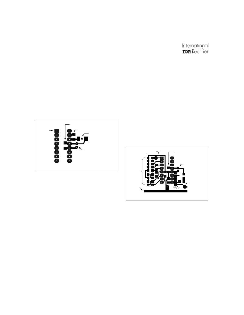
�Supply� Bypassing� and� PC� Board�
�Layout� Rules�
�Component� selection� and� placement� on� the� pc�
�board� is� extremely� important� when� using� power�
�control� ICs.� V� CC� should� be� bypassed� to� COM� as� close�
�to� the� IC� terminals� as� possible� with� a� low� ESR/ESL�
�capacitor,� as� shown� in� Figure� 1� below.�
�Connecting� the� IC� Ground� (COM)�
�to� the� Power� Ground�
�Both� the� low� power� control� circuitry� and� low� side�
�gate� driver� output� stage� grounds� return� to� this� lead�
�within� the� IC.� The� COM� lead� should� be� connected� to�
�the� bottom� terminal� of� the� current� sense� resistor� in�
�the� source� of� the� low� side� power� MOSFET� using� an�
�individual� pc� board� trace,� as� shown� in� Figure� 2.� In�
�addition,� the� ground� return� path� of� the� timing�
�IR21571�
�pin� 1�
�C� VCC� (surface� mount)�
�C� BOOT� (surface� mount)�
�D� Boot� (surface� mount)�
�components� and� V� CC� decoupling� capacitor� should�
�be� connected� directly� to� the� IC� COM� lead,� and� not�
�via� separate� traces� or� jumpers� to� other� ground� traces�
�on� the� board.�
�C� VCC� (through� hole)�
�Figure� 1:� Supply� bypassing� PCB� layout� example�
�timing�
�components�
�IR21571� pin� 1�
�C� VCC� (surface� mount)�
�C� VCC� (through� hole)�
�A� rule� of� thumb� for� the� value� of� this� bypass� capacitor�
�is� to� keep� its� minimum� value� at� least� 2500� times� the�
�value� of� the� total� input� capacitance� (Ciss)� of� the�
�V�
�BUS�
�return�
�R�
�CS�
�(through� hole)�
�power� transistors� being� driven.� This� decoupling�
�capacitor� can� be� split� between� a� higher� valued�
�Figure� 2:� COM� lead� connection� PCB� layout� example�
�to� the� V� CC� and� COM� terminals� will� work� well.�
�electrolytic� type� and� a� lower� valued� ceramic� type�
�connected� in� parallel,� although� a� good� quality�
�electrolytic� (e.g.,� 10� μ� F)� placed� immediately� adjacent� This� connection� technique� prevents� high� current�
�ground� loops� from� interfering� with� the� sensitive� timing�
�component� operation,� and� allows� the� entire� control�
�In� a� typical� application� circuit,� the� supply� voltage� to� circuit� to� reject� common-mode� noise� due� to� output�
�the� IC� is� normally� derived� by� means� of� a� high� value� switching.�
�startup� resistor� (1/4W)� from� the� rectified� line� voltage,�
�in� combination� with� a� charge� pump� from� the� output�
�of� the� half-bridge.� With� this� type� of� supply�
�arrangement,� the� internal� 15.6V� zener� clamp� diode�
�from� V� CC� to� COM� will� determine� the� steady� state� IC�
�supply� voltage.�
�8�
�www.irf.com�
�相关PDF资料 |
PDF描述 |
|---|---|
| IR21593STRPBF | IC BALLAST CTLR DIMMING 16-SOIC |
| IR2159STR | IC BALLAST CONTROL DIM 16-SOIC |
| IR2161STRPBF | IC HALOGEN CONVERTER CTLR 8-SOIC |
| IR2166S | IC PFC/BALLAST CONTROL 16-SOIC |
| IR2167STRPBF | IC PFC BALLAST CTLR 20-SOIC |
相关代理商/技术参数 |
参数描述 |
|---|---|
| IR21571STRPBF | 功能描述:功率驱动器IC Ballast Cntrl Thrml Ovrload Prot RoHS:否 制造商:Micrel 产品:MOSFET Gate Drivers 类型:Low Cost High or Low Side MOSFET Driver 上升时间: 下降时间: 电源电压-最大:30 V 电源电压-最小:2.75 V 电源电流: 最大功率耗散: 最大工作温度:+ 85 C 安装风格:SMD/SMT 封装 / 箱体:SOIC-8 封装:Tube |
| IR2157S | 制造商:未知厂家 制造商全称:未知厂家 功能描述:Ballast Control. Below Resonance Protection. Thermal Overload Protection. Protection from Failure to Strike. Programmable Preheat Time and Run Frequency. Programmable Deadtime in a 16-lead SOIC Narrow package |
| IR2159 | 制造商:IRF 制造商全称:International Rectifier 功能描述:DIMMING BALLAST CONTROL IC |
| IR21591 | 制造商:IRF 制造商全称:International Rectifier 功能描述:DIMMING BALLAST CONTROL IC |
| IR21591S | 制造商:IRF 制造商全称:International Rectifier 功能描述:DIMMING BALLAST CONTROL IC |
发布紧急采购,3分钟左右您将得到回复。